In this article we will take a look at how to do tessellation on the GPU with Metal. Tessellation is a powerful technique for generating geometry dynamically with many use cases from CAD/CAM to game development and beyond. This article discusses the fundamentals of tessellation and how to do it in Metal; future articles will showcase specific use cases.
The source code for this article is available here. It consists of a Mac app written in Swift that shows how to dynamically subdivide a cube and icosahedron, optionally smoothing the resulting shapes into approximate spheres.
A Brief Introduction to Tessellation
Tessellation is a form of geometry amplification: programmatically turning geometry into more geometry.
With ordinary draw calls, we render primitives such as triangles, lines, or points. Conversely, when tessellating, our draw calls are denominated in patches. A patch is a triangular or quadrilateral domain that can be subdivided by the GPU to produce triangles. The number of triangles generated by a patch is controlled by configuring a fixed-function stage of the pipeline called the tessellator. The tessellated triangles then pass through the remainder of the graphics pipeline (vertex shader, rasterizer, etc.) on their way to the framebuffer.
Motivating Tessellation
If you’ve used Metal to render 3D meshes composed of triangles, you may have encountered a situation where the mesh you wanted to draw was too large to fit into memory. There are many techniques that can be used to reduce the memory footprint of geometry.
One possible approach is to decimate (reduce) the geometry of the mesh while producing a texture map whose texels store fine-grained surface normals. This is called normal mapping. Normal mapping does not refine the silhouette edge the mesh, so the effect is not always convincing, but it is a great way to reduce the number of vertices in a mesh.
Another technique that allows you to get more mileage out of less geometry is instancing, which draws the same mesh multiple times without duplicating the vertex data in memory. Instancing is best used when the repetition of meshes won’t be noticeable, as when rendering debris, foliage, or crowds.
Tessellation allows you to refine your geometry on the fly, without requiring you to allocate additional memory to hold the resulting vertices. Once the geometry is subdivided, you can use techniques like displacement mapping to reposition the refined vertices, creating more detail across the surface, including along silhouette edges.
With tessellation, you can overcome some of the limitations of vertex attribute storage by generating additional geometry on the GPU at runtime.
Patches
Metal supports two patch types: triangle and quad (short for quadrilateral). Ultimately, tessellation always produces triangles, but you can select between these patch types based on the natural topology of your base geometry. Some types of modeling are based on subdivision of quads, such as Catmull–Clark subdivision surfaces, which are common in computer-aided design and animated film.
When authoring meshes intended for tessellation, it is important to ensure that your asset pipeline does not automatically triangulate your patch geometry. Quads are not broadly supported as a basic primitive by modern graphics APIs, so some formats such as glTF don’t currently allow them to be encoded. The assets included with the sample project have been hand-authored in OBJ format so that the patches are loaded in the expected format. We will discuss this in greater detail below.
Tessellation Factors
Tessellation factors are numbers that specify how the patch domain should be divided, including how many times each patch should be subdivided, and where divisions occur along the patch boundaries.
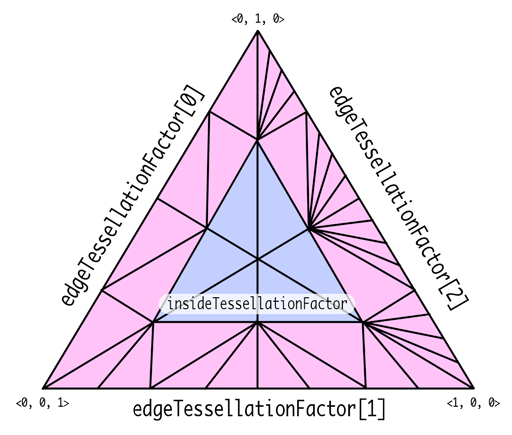
For a triangle patch, we specify three edge tessellation factors, which describe how the outer edges are refined, and one inside tessellation factor, which describes the subdivision of the interior region of the patch.
In the figure below, we label the edge or area affected by each tessellation factor in a triangle patch. Note that each edge and inner factor can be set independently, giving detailed control over the amount of generated geometry.
For a quad patch, we specify four edge tessellation factors (one for each outer edge) and two inside tessellation factors, which respectively describe the horizontal and vertical subdivision of the patch interior.
In the figure below we again label each outer and interior edge with its corresponding tessellation factor.

We will see momentarily how to store these factors and how to generate them on the GPU.
The Tessellation Pipeline
Tessellation is performed in the context of the broader graphics pipeline. In this subsection, we assume familiarity with how to write vertex and fragment functions to do ordinary rasterization, and proceed to describe how tessellation is incorporated into this pipeline.
To start with, here is a simplified view of the familiar rasterization-based graphics pipeline:

When tessellating, we first need to determine the tessellation factors of the patches we wish to draw. This can be done with a compute shader, but using a shader is not mandatory.
Tessellation factors are consumed by the fixed-function tessellator stage, which produces the subdivided geometry and passes it down the pipeline to the vertex function.
A post-tessellation vertex function is similar to an ordinary vertex function, except that instead of operating on vertex attributes, it operates on control point attributes and the coordinates of the vertex within the patch domain.
The figure below shows how these parts fit into the pipeline. Note that the tessellation factor compute function has a dashed outline to signify that it is optional. In the absence of this compute function, the factors can simply be written into a buffer from the CPU.

Tessellation in Metal
Now that we’re familiar with the motivation for tessellation and some of the foundational concepts, let’s look at how to actually do tessellation with Metal.
Our approach consists of several tasks:
- Load patch data from a 3D model file
- Write a tessellation factor function and build a compute pipeline state
- Run the compute pipeline to calculate our tessellation factors
- Write a post-tessellation vertex function and build a render pipeline state
- Draw with the render pipeline state to tessellate and rasterize the patches
Loading Patch Data with Model I/O
The Model I/O framework provides a consistent, robust API for loading 3D model assets efficiently. We have previously used the framework to demonstrate the fundamentals of modern rendering in Metal, and we use it again here to load our patch data.
Model I/O is graphics API-agnostic; it does not depend directly on Metal. However, since we will be rendering with Metal, we want to ensure that our control point data lives in Metal buffers. We do this by creating an instance of MTKMeshBufferAllocator, a utility class from the MetalKit framework. Model I/O uses this allocator to create MTKMeshBuffer objects that store mesh data.
We initialize an MTKMeshBufferAllocator with an MTLDevice:
let bufferAllocator = MTKMeshBufferAllocator(device: device)
To inform Model I/O about our desired control point data arrangement, we create a vertex descriptor, an instance of MDLVertexDescriptor. We want packed, interleaved vertex positions and normals, so we create a descriptor with two attributes and one layout:
let vertexDescriptor = MDLVertexDescriptor()

vertexDescriptor.attributes_[0].name = MDLVertexAttributePosition
vertexDescriptor.attributes_[0].format = .float3
vertexDescriptor.attributes_[0].offset = 0
vertexDescriptor.attributes_[0].bufferIndex = 0

vertexDescriptor.attributes_[1].name = MDLVertexAttributeNormal
vertexDescriptor.attributes_[1].format = .float3
vertexDescriptor.attributes_[1].offset = 12
vertexDescriptor.attributes_[1].bufferIndex = 0

vertexDescriptor.layouts_[0].stride = 24
Now that we have a buffer allocator and vertex descriptor, we can use the MDLAsset class to load the contents of our OBJ files. We will use the MDLAsset(url:vertexDescriptor:bufferAllocator: preserveTopology:error:) initializer.
The most important parameter to the MDLAsset initializer is the preserveTopology flag. This tells Model I/O not to triangulate the data on import, which will preserve our tessellation-ready patches.
var error: NSError?
let asset = MDLAsset(url: assetURL,
                     vertexDescriptor: vertexDescriptor,
                     bufferAllocator: bufferAllocator,
                     preserveTopology: true,
                     error: &error)
Now that we have an MDLAsset, we need to extract a mesh and submesh from it so we have access to its control point data and, optionally, its control point index data.
let mesh = asset.childObjects(of: MDLMesh.self).first as! MDLMesh
let submesh = mesh.submeshes?.firstObject as! MDLSubmesh
From the mesh and submesh, we can determine the number of control points per patch, the number of patches, and the buffer resources we should use to draw.
To keep things tidy, the sample code wraps these resources in a class: the TessellatedMesh type. A tessellated mesh is nothing but a container for the data used to draw a collection of patches. It holds the following properties:
let patchCount: Int
let controlPointsPerPatch: Int
let controlPointBuffer: MTKMeshBuffer
let controlPointIndexBuffer: MTKMeshBuffer?
let controlPointIndexType: MTLTessellationControlPointIndexType
let tessellationFactorBuffer: MTLBuffer
let tessellationFactorBufferOffset: Int
…
Most of these properties are populated with the data we get from the asset:
controlPointsPerPatch = controlPointCount(for: submesh)
patchCount = mesh.vertexCount / controlPointsPerPatch
controlPointBuffer = mesh.vertexBuffers[0] as! MTKMeshBuffer
// Ignore indices for now
controlPointIndexBuffer = nil
controlPointIndexType = .none
We also need to create a buffer to store the tessellation factors for each patch. Before we do that, we’ll introduce how Metal represents these tessellation factors in memory.
Tessellation Factor Structures and Buffers
Tessellation factors are stored together in structure types that are available to both shaders (MSL) and app code (Objective-C/Swift). For triangle patches, the struct looks like this (in MSL):
struct MTLTriangleTessellationFactorsHalf {
  half edgeTessellationFactor[3];
  half insideTessellationFactor;
};
Tessellation factors are half-precision floating-point numbers, which are each 16 bits, so the size of this struct is 8 bytes.
The structure for quad patch tessellation factors is similar; it simply has a different number of edge and inside factors:
struct MTLQuadTessellationFactorsHalf {
  half edgeTessellationFactor[4];
  half insideTessellationFactor[2];
};
Suppose we want to draw a set of  quad patches. We would allocate a buffer large enough to contain instances of the
 MTLQuadTessellationFactorsHalf struct:
tessellationFactorBuffer = device.makeBuffer(length: MemoryLayout<MTLQuadTessellationFactorsHalf>.stride * N, options: .storageModePrivate)
This buffer can be created in private storage because we will only interact with it via shaders, rather than reading or writing it from the CPU.
Now that we know how tessellation factors are stored and have created a buffer to store them, we can talk about how to generate tessellation factors on the GPU.
The Tessellation Factor Compute Shader
The job of a tessellation factor compute shader is to produce a set of tessellation factors. Specifically, a tessellation factor compute function fills in one or more of the MTLTriangleTessellationFactorsHalf or MTLQuadTessellationFactorsHalf structures we just introduced.
To populate the tessellation factor buffer, we write a compute function. The signature of one such function is presented here:
kernel void compute_tess_factors(
    device MTLQuadTessellationFactorsHalf *factorsArray [[buffer(0)]],
    uint patchIndex [[thread_position_in_grid]])
Like all compute shaders, this function is prefixed with kernel and returns void. The factor buffer pointer is in the device address space, which makes it writeable.
We take the thread position of the current invocation to be an index into the factor buffer. Each compute thread calculates the factors for one patch. We can index into the patch factors array to form a mutable reference to the current thread’s factors struct:
{
    device MTLQuadTessellationFactorsHalf &patchFactors = factorsArray[patchIndex];
    patchFactors.edgeTessellationFactor[0] = …;
    patchFactors.edgeTessellationFactor[1] = …;
    patchFactors.edgeTessellationFactor[2] = …;
    patchFactors.edgeTessellationFactor[3] = …;
    patchFactors.insideTessellationFactor[0] = …;
    patchFactors.insideTessellationFactor[1] = …;
}
Compute functions can be as complex as required to achieve the desired effect. The actual calculation is not shown above, but it could be as simple as writing the same value to every factor. Or, you might determine the factors based on the patch’s distance from the camera, your overall geometry budget, or any other useful parameters.
This pattern for writing a tessellation factor function also applies to triangle patches; in this case the buffer is taken to be a pointer to MTLTriangleTessellationFactorsHalf.
The Tessellation Factor Compute Pipeline State
To execute the tessellation factor compute function, we first create a compute pipeline state. This consists of requesting a reference to the compute function from an MTLLibrary and asking the device for a compute pipeline state:
let computeFunction = library.makeFunction(name: "compute_tess_factors")!
let computePipelineState = try device.makeComputePipelineState(function: computeFunction)
To populate the tessellation factors for all of our patches, we dispatch a one-dimensional compute grid using a compute command encoder:
computeCommandEncoder.setComputePipelineState(computePipelineState)
computeCommandEncoder.setBuffer(tessellationFactorBuffer, offset: 0, index: 0)
// Bind additional resources as needed
…
let threadgroupSize = MTLSize(width: computePipelineState.threadExecutionWidth, height: 1, depth: 1)
let threadCount = MTLSize(width: patchCount, height: 1, depth: 1)
computeCommandEncoder.dispatchThreads(threadCount, threadsPerThreadgroup: threadgroupSize)
The threadgroup width is the execution width of the pipeline state (commonly 32), and the total grid width is the number of patches. This causes the computation to occur in parallel, since each factor calculation is independent.
If the tessellation factors need to be dynamic, we can run this function once per frame to update them. Alternatively, we can run this function just once and reuse the results.
The tessellation factors will be consumed by the tessellator to produce the triangles that are fed to the rest of the pipeline, so let’s now look at the next stage of that pipeline.
The Post-Tessellation Vertex Shader
The post-tessellation vertex function’s job is to calculate the vertex position in clip space. There are a few notable differences between ordinary vertex functions and post-tessellation functions, which we will detail in this subsection.
To illustrate these differences, here is an example function signature for a quad patch vertex function:
[[patch(quad, 4)]]
vertex VertexOut vertex_subdiv_quad(
    PatchIn patch [[stage_in]],
    …
    float2 positionInPatch [[position_in_patch]])
Post-tessellation vertex functions are prefixed with the patch attribute. The first attribute parameter indicates the patch type (quad or triangle), while the second parameter is the number of control points per patch.
Note that the control point count does not have to equal the number of vertices in the patch primitive. That is, a quad patch is not limited to exactly 4 control points. Rather, a post-tessellation vertex function can consume between 0 and 32 control points for any patch type.
More specifically, the number of control points is determined by how the asset was authored and the interpolation algorithm used to turn control points into vertices. The sample code coincidentally uses 3 control points per triangle patch and 4 control points per quad patch to implement simple linear interpolation schemes.
The vertex function takes a parameter attributed with stage_in to indicate that we want Metal to fetch control point attributes for us. Unlike ordinary vertex attributes, control points must be wrapped in the patch_control_point<T> template type. A basic control point wrapper might look like this:
struct ControlPoint {
    float3 position [[attribute(0)]];
    float3 normal   [[attribute(1)]];
};

struct PatchIn {
    patch_control_point<ControlPoint> controlPoints;
};
As with regular vertex function inputs, the members of the ControlPoint type correspond by index to the attributes specified in the vertex descriptor.
The final difference between ordinary vertex functions and post-tessellation vertex functions is the position_in_patch attribute. A parameter with the position_in_patch attribute contains the coordinates of the current vertex in the current tessellated primitive within the domain of the current patch. How these coordinates are interpreted depends on the patch type.
For a quad patch, the position_in_patch parameter is a float2 value containing the normalized (0-1) uv coordinates in the rectangular domain of the patch. For a triangle patch, it is a float3 value containing the barycentric coordinates of the current vertex in the patch. Refer to the figures above for an illustration of these patch domain spaces.
In either case, we want to load our control point attributes and interpolate among them to produce the position of the current vertex. We will look at each patch type in turn.
To calculate a tessellated position in a quad patch, we load the patch’s control points and use bilinear interpolation to find the current vertex’s position:
[[patch(quad, 4)]]
vertex VertexOut vertex_subdiv_quad(
     PatchIn patch [[stage_in]],
     …
     float2 positionInPatch [[position_in_patch]])
{
    float3 p00 = patch.controlPoints[0].position;
    float3 p01 = patch.controlPoints[1].position;
    float3 p10 = patch.controlPoints[3].position;
    float3 p11 = patch.controlPoints[2].position;
    float3 modelPosition = bilerp(p00, p01, p10, p11, positionInPatch);

    // calculate clip-space position, etc.
    …
}
The vertex function for a triangle patch is similar, but because of the triangular shape of the domain, we use barycentric interpolation rather than bilinear:
[[patch(triangle, 3)]]
vertex VertexOut vertex_subdiv_tri(
    PatchIn patch                  [[stage_in]],
     …
    float3 positionInPatch         [[position_in_patch]])
{
    float3 p0 = patch.controlPoints[0].position;
    float3 p1 = patch.controlPoints[1].position;
    float3 p2 = patch.controlPoints[2].position;
    float3 modelPosition = baryinterp(p0, p1, p2, positionInPatch);

    // calculate clip-space position, etc.
    …
}
The bilerp and baryinterp utility functions are not reproduced here for brevity but can be found in the sample code.
The remainder of the vertex function proceeds as usual. We compute the clip-space position from the model position using a model-view-projection matrix provided in a constant buffer, and produce any other interpolated attributes we want to use in the fragment shader (such as normals for lighting).
The Tessellation Render Pipeline State
We can now build a render pipeline state that runs our post-tessellation vertex function for every tessellated vertex and shades the resulting fragments.
There are a few important properties on the render pipeline descriptor that are not used for regular rasterization, so we will look at those first.
The tessellationPartitionMode property determines the algorithm that is used to subdivide patches. The foregoing discussion has assumed the default partition mode of pow2. Other partition modes are useful for various use cases but are beyond the scope of this article. They are documented here.
The tessellationFactorStepFunction determines how frequently new factors are fetched from the tessellation factor buffer. A value of .constant means that the same set of factors is used for all patches, while a value of .perPatch means that each patch has its own set of factors in the buffer. (There are other values that become relevant when instancing, but these are beyond the scope of this article.)
The tessellationControlPointIndexType property is relevant when control points are indexed and takes a value of .none, .uint16, or .uint32. The sample code optionally demonstrates use of indexed patch rendering, but use of this property is not mandatory.
Here is how the sample code configures the tessellation properties of the render pipeline state by default:
let renderPipelineDescriptor = MTLRenderPipelineDescriptor()
// Use the (default) power-of-two partition mode
renderPipelineDescriptor.tessellationPartitionMode = .pow2
// Fetch tessellation factors for each patch individually
renderPipelineDescriptor.tessellationFactorStepFunction = .perPatch
// Don't use a control point index buffer
renderPipelineDescriptor.tessellationControlPointIndexType = .none
…
One other small difference between ordinary and tessellating pipeline states relates to the vertex descriptor. Since we are asking Metal to automatically fetch control point data from our attribute buffers, we use the step function property of our buffer layout to fetch data per control point rather than per vertex.
The complete code for adapting the Model I/O vertex descriptor for tessellation is:
let vertexDescriptor = MTKMetalVertexDescriptorFromModelIO(mdlVertexDescriptor)!
vertexDescriptor.layouts[0].stepRate = 1
vertexDescriptor.layouts[0].stepFunction = .perPatchControlPoint
With this change made, we set the vertexFunction, fragmentFunction, and vertexDescriptor properties of the descriptor, configure render target pixel formats and blending properties, and finally create a render pipeline state:
let renderPipelineState = try device.makeRenderPipelineState(descriptor: renderPipelineDescriptor)
Tessellated Draw Calls
At last, we are ready to draw some tessellated patches. There are a pair of methods on MTLRenderCommandEncoder that enable tessellated draw calls, one for non-indexed control points, and one for indexed control points.
In both of these cases, we configure the render command encoder similarly: set the render pipeline state, set any control point attribute buffers, set the tessellation factor buffer, and configure any other fixed-function state and arguments:
renderCommandEncoder.setVertexBuffer(controlPointBuffer, offset: 0, index: 0)
// Bind constant buffers, etc.
…
renderCommandEncoder.setTessellationFactorBuffer(tessellationFactorBuffer, offset: 0, instanceStride: 0)
// Set other fixed-function state…
…
The simple case is non-indexed tessellation: we use the drawPatches(numberOfPatchControlPoints: patchStart: patchCount: patchIndexBuffer: patchIndexBufferOffset: instanceCount: baseInstance:) method to draw the number of patches we want to render.
The patchIndexBuffer parameter is an optional MTLBuffer containing the indices of patches to draw. This is distinct from the patch control points themselves being indexed and supports use cases we won’t cover here.
renderCommandEncoder.drawPatches(
    numberOfPatchControlPoints: controlPointsPerPatch,
    patchStart: 0,
    patchCount: patchCount,
    patchIndexBuffer: nil,
    patchIndexBufferOffset: 0,
    instanceCount: 1,
    baseInstance: 0)
If we do want to use indexed control points, we call the drawIndexedPatches(numberOfPatchControlPoints: patchStart: patchCount: patchIndexBuffer: patchIndexBufferOffset: controlPointIndexBuffer: controlPointIndexBufferOffset: instanceCount: baseInstance:) method.
renderCommandEncoder.drawIndexedPatches(
    numberOfPatchControlPoints: controlPointsPerPatch,
    patchStart: 0,
    patchCount: patchCount,
    patchIndexBuffer: nil,
    patchIndexBufferOffset: 0,
    controlPointIndexBuffer: controlPointIndexBuffer,
    controlPointIndexBufferOffset:0,
    instanceCount: 1,
    baseInstance: 0)
Each of these methods supports instanced drawing via the instanceCount and baseInstance parameters; use of these parameters is beyond the scope of this article, but proceeds similarly to other uses of instanced rendering demonstrated elsewhere on this site.
The Sample App
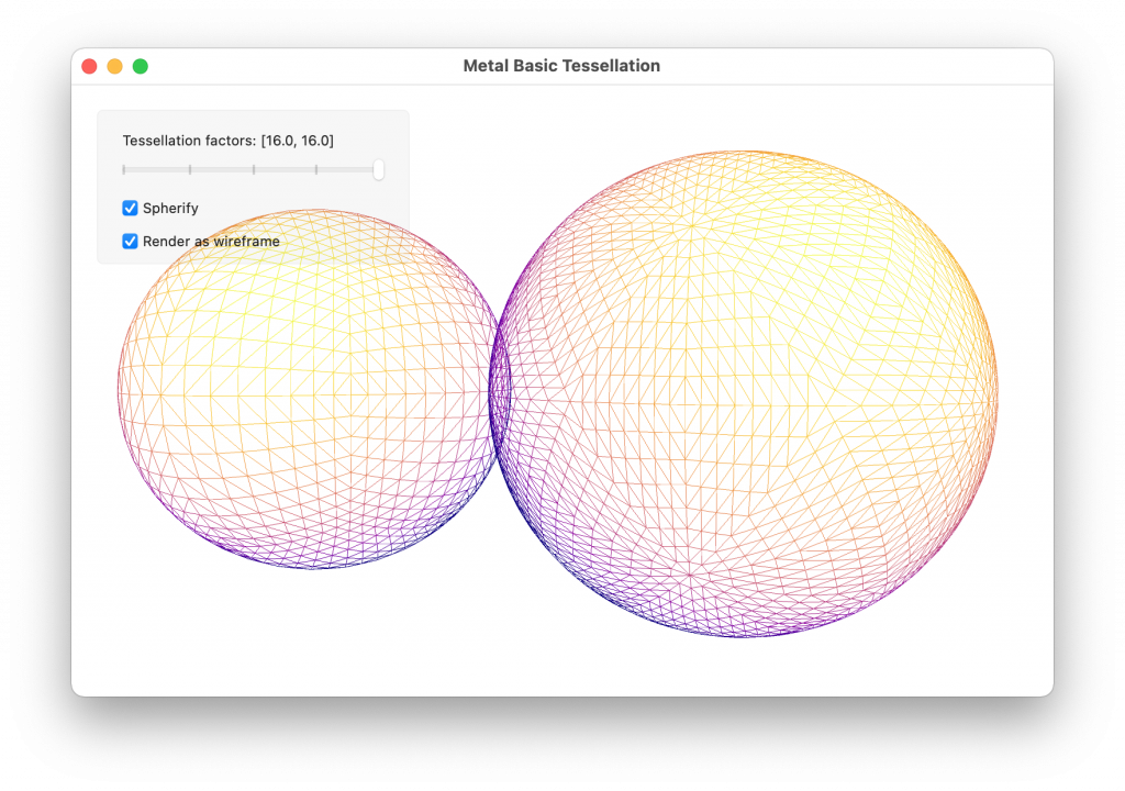
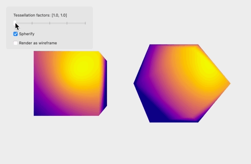
The sample app consists of a demonstration of Metal tessellation: a cube and icosahedron are tessellated according to the tessellation factors provided by the app. For simplicity, the edge and inner factors are constrained to be the same. The shapes can optionally be rendered with flat shading, or per-vertex normals can be generated on the fly to produce a smooth surface appearance. Another toggle controls whether the surfaces are rendered as wireframes or with solid geometry.
Great Tutorial!!
wondering how would go about animating like a wave in a quad(plane)? maybe a procedural height map?
If the wave simulation is simple enough (such as just a sum of cosine waves), this could be done by calculating the wave height at each vertex in the post-tessellation vertex shader. If the simulation is dependent on previous or adjacent values of the heightmap (as it would be for many fluid models), you could run a compute shader to build a procedural heightmap texture as you suggest, then sample that in the vertex shader.
If you also need the height on the CPU (to have a character or other object stay atop the wave), it’s probably best to have a CPU-based implementation of the simulation, rather than doing the calculation on the GPU and reading it back on the CPU (which will introduce latency and/or stalling), or doing the calculation on the CPU and then uploading it to the GPU every frame (which can be costly in terms of time/bandwidth). If you want the height at a single point on the CPU but don’t want to run the simulation on both the CPU and GPU, and you can handle a little latency (2-3 frames), you can point-sample the heightmap on the GPU with a compute shader (basically ray-casting), store the height in a small buffer, and then read that single value back on the CPU.
The legend that single handedly carry the metal tutorial community 🙂
Looking forward to your updated book: Metal by example.
Hi, I would like to know if this technique can be used for triangulating flattened polygons on the GPU. Any ideas?
If by flattened, you mean something like a closed polyline that has been flattened from a closed contour (such as a Bezier spline representing a glyph from a font), it’s not immediately obvious to me how that would work. Hardware tessellation is limited by the fact that it only supports a couple of fixed topologies (triangle and quad). You could use a more general routine like constrained Delaunay triangulation, as implemented in libraries like libtess2 for such a case. I’m not aware of any GPU-based implementations for generalized tessellation of this sort, though perhaps they exist.
Yes, that’s exactly what I meant – I have implemented Delaunay triangulation to convert flattened contours, but I am looking for other options on how to make it more efficiently.
I will investigate further.
Covers exactly what I was looking for, thanks.