Metal 3, introduced by Apple at WWDC 2022, brought with it a significant number of features that enable modern rendering techniques, faster resource loading, and flexible shader compilation. It also includes an all-new geometry pipeline that unlocks novel rendering techniques by allowing developers to bypass most of the traditional vertex processing steps and submit geometry directly to the rasterizer.
In this article, we will explore the features of the new geometry pipeline in Metal 3, how it works, and its use cases. We will then go into more depth on how to use mesh shaders to implement meshlet culling, an important feature of modern GPU-driven rendering engines.
Download the sample code for this article here. Some implementation details are omitted from this exposition for the sake of brevity, and there’s no substitute for reading the code.
A New Geometry Pipeline
If you are accustomed to using Metal’s basic rendering features, you have almost certainly used vertex descriptors. Vertex descriptors indicate how vertex attributes are laid out in vertex buffers. Including a vertex descriptor in your render pipeline descriptor allows the shader compiler to inject code (a vertex function preamble) that automatically loads current vertex’s data into the vertex function’s stage-in argument. This feature is called vertex fetch. By contrast, when not using a vertex descriptor, you are responsible for manually loading vertex data from vertex buffers yourself; this is called vertex pull.
Relying on vertex fetch simplifies writing vertex functions. Without it, you not only have to manually load data; you also must manually perform any necessary conversions (e.g., from normalized integer representations to floating-point, or from 3-element vectors to 4-element vectors). But this approach is not without downsides.
Motivation
The vertex processing portion of the traditional programmable graphics pipeline is suboptimal for many kinds of scenes. Because draw calls have an encoding overhead, it has historically been advised to reduce the draw call count. This in turn means that each draw call might draw geometry that spans a large area and contains triangles oriented in arbitrary directions. Because vertices must be processed before they are assembled into primitives, memory bandwidth is wasted on loading vertex data that belongs to triangles that will then immediately be culled. Furthermore, because vertex functions operate at the vertex level, they have no way to reason about primitives and no way to efficiently reject primitives midstream.
Even for triangles that survive culling, the traditional approach often underutilizes the post-transform vertex cache. This is because index buffers are often not sorted such that vertices belonging to adjacent primitives are referenced by adjacent indices. This leads to indexed meshes looking a lot like triangle soup from the vertex cache’s perspective.
Since 2015 there has been an increasing emphasis on using compute shaders to determine triangle visibility before passing geometry to the rasterizer. Graham Wihlidal’s influential GDC 2016 talk is a useful reference to get acquainted with the mindset of compute-based geometry processing, though it is heavily technical and specific to AMD’s GCN architecture. In our discussion of meshlet culling below, we will implement a couple of these ideas in Metal.
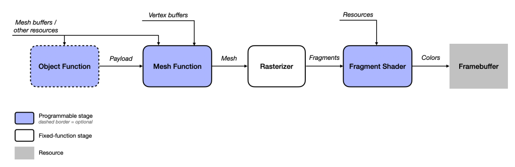
As compute-based geometry processing techniques became more common, GPU vendors and graphics API designers began incorporating these ideas into their products, giving rise to modern geometry pipelines. Apple’s implementation of compute-oriented geometry processing adds two programmable stages to the graphics pipeline that can run in-line (in the same command encoder) with rasterization. These stages are object shaders and mesh shaders, and we will look at each in turn.
Object Functions
The word “mesh” is somewhat ambiguous. We often think of meshes as 3D models, which might have any number of submeshes, each of which often has distinct material properties.
Within the context of object and mesh shaders, the word “mesh” has a more particular meaning. It is a small collection of vertices, indices, and per-primitive data. A mesh might be a sprig of grass, a strand of hair, or some other shape consisting of at most a few dozen vertices and a few dozen triangles. The reason meshes are restricted in size is that they need to be able to fit into threadgroup memory for efficient processing.
The chief idea behind object shaders is to give the programmer the opportunity to decide which chunks of geometry should proceed through the rest of the pipeline. Just like compute grids, objects are abstract entities that can represent any collection of work that makes sense in your application. An object might be a collection of models, a single submesh of a larger model, a patch of terrain, or any other unit of work that might give rise to one or more meshes.
An essential idea in object shaders is the notion of amplification. Because of the object shader execution model, each object can spawn zero, one, or many meshes1.
Just as each vertex or fragment is processed by an invocation of a vertex or fragment function, an object is processed by an invocation of an object function. Similar to how we dispatch a compute grid by specifying a threadgroup size and a threadgroup count and a compute pipeline, we draw objects by calling a method on a render command encoder that takes the size of the object threadgroup to execute and how many object threadgroups should be launched.
Each object thread produces a payload, a set of arbitrary data that is passed to a mesh function invocation for further processing. We will look at how to write object shaders below, but the main point is: object shaders achieve amplification by determining how many meshes should be produced by the object and providing payload data to each subsequently launched mesh thread.
Mesh Functions
Mesh functions are a new type of shader function that can operate on a group of vertices instead of individual vertices. As mentioned above, a mesh—in this context—is a parcel of vertices, indices, and per-primitive data that is produced by a mesh shader and passed on to the fixed-function rasterizer.
Just as an object function can produce a payload describing zero or more meshes, a mesh function can produce a mesh comprising zero or more primitives (which are stitched together from its constituent vertices). Each mesh threadgroup provoked by an object function produces a single (potentially empty) mesh.
Collectively, the threads of a mesh threadgroup perform the following work:
- Copy vertex data into the output mesh
- Copy index data into the output mesh
- Copy per-primitive data into the output mesh
- Set the total number of primitives contained by the mesh
How to divide the work of mesh generation across threads is up to you. It is possible for a single thread to do all of the work, especially for a small mesh. Often it will be more efficient to share the load across threads, with each thread generating a vertex, a few indices, and/or a primitive.
We will see an in-depth example of how to divide the work up in the section on meshlet culling below.
Mesh Shader Use Cases
Mesh shaders are useful whenever you desire to process geometry at a coarser level than individual triangles. Mesh shaders can generate procedural geometry such as hair, fur, foliage, or particle traces. They can be used to select among precomputed levels of detail based on metrics such as screen-space coverage and distance to the camera. And they can take advantage of spatial coherency to produce meshlets that fully exploit vertex reuse and avoid the wasted work of processing back-facing triangles.
We will look at each of these use cases in turn.
Procedural Geometry
One of the most significant use cases for mesh shaders is procedural geometry. Procedural geometry is a category of processes and techniques for generating geometry algorithmically rather than using premade assets. Instead of keeping a full representation of a shape in memory, mesh shaders can generate shapes on the fly, greatly increasing scene detail without increasing a scene’s memory footprint. Procedural methods have been used for many years in graphics, and their appeal increases with mesh shaders, as it is now possible to generate detailed geometry from a simplified representation without keeping the fully expanded geometry in memory. For an example of procedural geometry in the context of fur rendering, see the WWDC 2022 session on mesh shading.
LOD Selection
Another use case for mesh shaders is level of detail (LOD) selection. LOD selection is the process of selecting the appropriate level of detail for an object based on its distance from the camera or some other measure. Levels of detail can be computed in advance at a set of discrete levels (similar to mipmaps), or generated on-the-fly from a parametric representation, similar to fixed-function tessellation.
The sample code accompanying the WWDC session on mesh shaders mentioned above gives a rudimentary example of how to implement level of detail selection.
Now that we have mentioned a couple of possible use cases for mesh shaders—procedural geometry and level-of-detail selection—let’s dive deeper into an increasingly common use of the new geometry pipeline: meshlet culling.
Meshlets and Meshlet Culling
One of the most interesting use cases of mesh shaders is meshlet culling. To understand the virtues of this technique, we first need to know what a meshlet is.
Most 3D modeling packages produce assets in a handful of common formats (Wavefront .obj, glTF, USD[Z], etc.). Frequently, the meshes produced by these programs are unorganized lists of vertices and indices that are stitched together in a way that mirrors the program’s internal representation (rather than any kind of optimal ordering). If we load such an asset and render it, there’s a good chance a lot of triangles in a given mesh will be facing away from the camera, and there’s a decent chance that the index buffer will fail to reference vertices in an order that makes optimal use of the vertex cache.
What can we do? It has become more common in recent years to subdivide meshes into meshlets. As the name implies, meshlets are small meshes that collectively comprise a larger mesh. Importantly, meshlets are constructed for coherence. The vertices in a meshlet should be nearby one another, the meshlet’s indices should be laid out to match the vertices’ adjacency, and the normals of the meshlet’s triangles should point in the same general direction as one another.
Preprocessing Meshes to Meshlets
How do we turn a mesh into meshlets? Essentially, it comes down to reordering the mesh’s vertices so that spatially coherent vertices can be referenced in sequence, and building small index buffers that connect the vertices into triangles. Each meshlet, then, consists of a reference to a span of the original vertex buffer which contains its vertices and a list of index triples that comprise its triangles. Since meshlets can only reference a limited number of vertices, these indices are usually smaller than the 16 to 32 bit indices that we normally use when doing indexed drawing. We use 8-bit unsigned integers as our indices in the sample code.
The open-source meshoptimizer library is a flexible, efficient tool for dividing meshes into meshlets. We will not delve into all of meshoptimizer’s features (there are many); instead we will use its simplest meshlet generation function, meshopt_buildMeshlets. This function takes an indexed mesh or submesh and produces the following:
- A meshlet vertex list, which maps optimally ordered vertices to their positions in the original vertex list,
- A meshlet triangle list, which is a list of 8-bit indices, three for each triangle,
- A list of meshlets, each of which references a span of vertices and a span of triangles,
- An approximate bounding sphere for each meshlet, and
- A cone representing the average orientation and spread of each meshlet’s vertex normals.
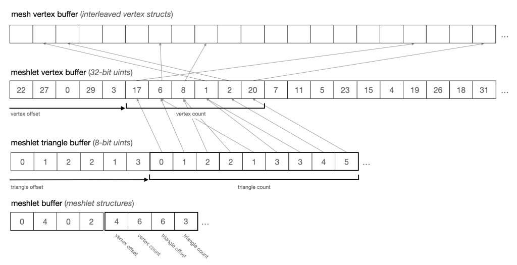
These outputs can be copied into Metal buffers and used directly by our object and mesh shaders. The figure below illustrates how the meshlet vertex buffer maps indices onto the original vertex buffer and how meshlets indicate their respective portions of the triangle list and vertex list. One interesting thing to note is that although the mapping from meshlet vertices (the top set of arrows) is rather incoherent (scattered in memory), the references made by indices within a meshlet are highly coherent and dense.
If you are curious about exactly how meshlets are generated, take a look at the meshletgen target in the sample code2. It’s a small command-line utility that uses Model I/O to load 3D models and produce preprocessed, “meshletized” meshes in a custom format.
Meshlet Culling Techniques
Once we have diced a mesh up into meshlets, how to we use them to make rendering more efficient? We will exploit the spatial coherence and normal coherence of meshlets together with object shaders to cull invisible meshlets before we spend any time processing their vertices. We will do this by performing frustum culling and normal cone culling.
Meshlet frustum culling is done by converting the viewing volume (i.e., the view frustum) into a set of planes against which we can cheaply test a meshlet’s bounding sphere. If the bounding sphere lies entirely in the negative half-space of any frustum plane, it is not in the viewing volume and can be culled.
Normal cone culling is slightly more involved. As part of the meshlet preprocessing phase, we generate a cone for each meshlet that is oriented along the average direction of its triangles’ normals. The width of the cone represents the maximal spread between the average normal and the vertex normals. With this information available, we can cull any meshlet whose normal cone faces sufficiently far away from the camera: if the normal cone does not contain the camera, then by definition, the camera cannot see any face in the meshlet. This is a form of aggregate backface culling that considers all triangles of a meshlet at once. It was introduced to graphics (as far as I’m aware) by Shirmun and Abi-Ezzi in 1993, in the context of Bezier patch culling.
We will look at how to implement these two culling techniques in an object shader below, after a brief introduction to object and mesh shader fundamentals.
Creating Mesh Render Pipeline States
Creating a render pipeline state that incorporates mesh shaders is very similar to creating a pipeline state using the traditional geometry pipeline. One chief difference is that because we will be manually loading the vertex data from buffers, we do not include a vertex descriptor.
In addition to the usual work of setting attachment pixel formats and blending state, we create our object, mesh, and fragment functions and set them on the corresponding properties of a render pipeline descriptor:
id<MTLFunction> objectFunction = [library newFunctionWithName:@"my_object_function"];
id<MTLFunction> meshFunction = [library newFunctionWithName:@"my_mesh_function"];
id<MTLFunction> fragmentFunction = [library newFunctionWithName:@"my_fragment_function"];

MTLMeshRenderPipelineDescriptor *pipelineDescriptor = [MTLMeshRenderPipelineDescriptor new];

pipelineDescriptor.objectFunction = objectFunction;
pipelineDescriptor.meshFunction = meshFunction;
pipelineDescriptor.fragmentFunction = fragmentFunction;
Then we can use the new -newRenderPipelineStateWithMeshDescriptor: options:reflection:error: method on our device to get a mesh render pipeline state:
[device newRenderPipelineStateWithMeshDescriptor:pipelineDescriptor
                                         options:MTLPipelineOptionNone
                                      reflection:nil
                                           error:&error]
Binding Object and Mesh Resources
Object and mesh functions can reference resources just like other kinds of shader functions. Mesh shaders add several new methods to the MTLRenderCommandEncoder protocol for this purpose, including these:
- (void)setObjectBytes:(const void *)bytes
                length:(NSUInteger)length
               atIndex:(NSUInteger)index;
- (void)setObjectBuffer:(id <MTLBuffer>)buffer
                 offset:(NSUInteger)offset
                atIndex:(NSUInteger)index;
- (void)setObjectTexture:(id <MTLTexture>)texture
                atIndex:(NSUInteger)index;
- (void)setMeshBytes:(const void *)bytes
              length:(NSUInteger)length
             atIndex:(NSUInteger)index;
- (void)setMeshBuffer:(id <MTLBuffer>)buffer
               offset:(NSUInteger)offset
              atIndex:(NSUInteger)index
- (void)setMeshTexture:(id <MTLTexture>)texture
               atIndex:(NSUInteger)index
Binding these resources works exactly as it does for other programmable stages.
Mesh Draw Calls
Understanding the structure of mesh draw calls is important, because the two-tier object/mesh execution model is the central aspect of the whole feature.
Metal mesh shaders add a few new draw methods to the MTLRenderCommandEncoder protocol. We will use just one of them, -drawMeshThreadgroups:threadsPerObjectThreadgroup: threadsPerMeshThreadgroup. Its signature looks like this:
-(void)drawMeshThreadgroups:(MTLSize)threadgroupsPerGrid
threadsPerObjectThreadgroup:(MTLSize)threadsPerObjectThreadgroup
  threadsPerMeshThreadgroup:(MTLSize)threadsPerMeshThreadgroup;
The threadgroupsPerGrid parameter tells Metal how many object threadgroups should be launched. Recall that each object threadgroup can ultimately launch zero, one, or many mesh threadgroups.
The threadsPerObjectThreadgroup parameter specifies the number of threads in each object threadgroup. As with compute kernels, this number should ideally be a multiple of the pipeline’s thread execution width, which you can retrieve from the render pipeline state’s objectThreadExecutionWidth property (it will commonly be 32 for current Apple GPUs).
The threadsPerMeshThreadgroup parameter specifies the number of threads in each mesh threadgroup. Like the previous parameter, it should be a multiple of thread execution width, which in this case is available as the meshThreadExecutionWidth property on MTLRenderPipelineState.
Note that we don’t specify the number of mesh threadgroups that will be launched by this draw call. After all, the entire point of object shaders is that the object function itself determines how many meshes to process.
Object Functions
The core structure of an object function looks like this:
[[object]]
void my_object_function(
    object_data Payload &object [[payload]],
    grid_properties grid)
{
    // Optionally populate the object's payload
    object.someProperty = ...;
    // Set the output grid's threadgroup count
    // (Only do this from one object thread!)
    grid.set_threadgroups_per_grid(uint3(meshCount, 1, 1));
}
An object function is prefixed with the new [[object]] attribute, which marks it as an object function.
An object function can take a parameter with the [[payload]] attribute. If present, this parameter must be a reference or pointer in the object_data address space. You control the type of this parameter; it is a structure containing whatever data your mesh shader might need to reference from its provoking object function. You populate this parameter however you like in the body of the function. We will use it below to tell the mesh shader which meshlets to render.
An object function also takes a parameter of type grid_properties, which has a single method: set_threadgroups_per_grid. This is the mechanism by which an object function causes grid threadgroups to be dispatched. Setting the threadgroup count to a non-zero value tells Metal it should launch that many threadgroups of the pipeline’s mesh function.
Importantly, only one thread in each object threadgroup should populate the threadgroup count. You might choose to add a parameter attributed with [[thread_position_in_threadgroup]] to your object function so you can check the current thread’s position and only write this property when the thread’s position is 0 (the sample code demonstrates this).
A Meshlet Culling Object Shader
The job of our meshlet culling object function is to perform meshlet culling as described in the section on culling techniques. For each meshlet in the mesh being rendered, we load just enough information to determine if it should be processed by the mesh function.
The discussion below assumes that whatever buffers are needed by a function have been bound appropriately to the current render command encoder; refer to the sample code if you care about the details.
Suppose we have the following structure that encapsulates all of the data belonging to a meshlet:
struct MeshletDescriptor {
    uint vertexOffset;
    uint vertexCount;
    uint triangleOffset;
    uint triangleCount;
    packed_float3 boundsCenter;
    float boundsRadius;
    packed_float3 coneApex;
    packed_float3 coneAxis;
    float coneCutoff;
    //...
};
The offset and count members refer to spans within the meshlet vertex buffer and meshlet triangle buffer, respectively. These are not used by the object shader. We will only be using the bounding properties and cone properties to perform culling.
We also need a custom type to store our object’s payload. This will simply consist of a list of meshlet indices that pass the culling tests:
struct ObjectPayload {
    uint meshletIndices[kMeshletsPerObject];
};
For the sake of exposition, I will slightly simplify the object function. See the sample code for the full implementation. Here’s the object function signature:
[[object]]
void object_main(
    device const MeshletDescriptor *meshlets [[buffer(0)]],
    constant InstanceData &instance          [[buffer(1)]],
    uint meshletIndex                        [[thread_position_in_grid]],
    uint threadIndex                         [[thread_position_in_threadgroup]],
    object_data ObjectPayload &outObject     [[payload]],
    mesh_grid_properties outGrid)
Notice that, as before, we have a payload parameter and a mesh grid properties parameter. We also take a pointer to a buffer containing our meshlet metadata and a small buffer containing some per-instance data.
In the object function body, we use our thread’s position in the object grid to retrieve the meshlet for which we will perform culling:
device const MeshletDescriptor &meshlet = meshlets[meshletIndex];
The particulars of frustum culling and normal cone culling are not important here; we perform both by calling out to small utility functions:
bool frustumCulled = !sphere_intersects_frustum(frustumPlanes, meshlet.boundsCenter, meshlet.boundsRadius);

bool normalConeCulled = cone_is_backfacing(meshlet.coneApex, meshlet.coneAxis, meshlet.coneCutoff, cameraPosition);
Since we are operating on many meshlets concurrently, we need to coordinate our object threads so that each one writes to the appropriate index of the payload array.
We start by combining our culling results into a single integer value:
int passed = (!frustumCulled && !normalConeCulled) ? 1 : 0;
We then use a prefix sum operation to determine how many threads with a smaller index than us passed their culling tests. If you aren’t acquainted with prefix sums, consult a resource such as this one.
int payloadIndex = simd_prefix_exclusive_sum(passed);
The resulting payload index tells our thread where it should write its meshlet’s index if the meshlet was not culled. So we consult the value of passed and then perform the write:
if (passed) {
    outObject.meshletIndices[payloadIndex] = meshletIndex;
}
The final job of the object function is to write out the mesh threadgroup count. As mentioned above, we only want one thread to do this, so we first compute the total number of non-culled meshlets, then—if we are the first thread in our object threadgroup—write out the number of mesh shader invocations:
uint visibleMeshletCount = simd_sum(passed);
if (threadIndex == 0) {
    outGrid.set_threadgroups_per_grid(uint3(visibleMeshletCount, 1, 1));
}
This concludes the body of the object function. The payload now contains the indices of the meshlets to be rendered, and the grid properties contain the number of mesh threadgroups to run.
Mesh Shader Outputs
A mesh function has a parameter of user-defined type that collects the vertices, indices, and per-primitive data generated by the function. The threads of the mesh’s threadgroup collaborate to produce this data. You define the type of the mesh by specifying a type that aggregates the vertex data and per-primitive data.
We start by defining the vertex data. This looks just like the return type of an ordinary vertex function.
struct MeshletVertex {
    float4 position [[position]];
    float3 normal;
    float2 texCoords;
};
In our simple example, the only per-primitive data we pass along is a color, for visualization purposes:
struct MeshletPrimitive {
    float4 color [[flat]];
};
These structures are incorporated into the output mesh by declaring a typedef that consists of a template instantiation of the metal::mesh class:
using Meshlet = metal::mesh<MeshletVertex, MeshletPrimitive, kMaxVerticesPerMeshlet, kMaxTrianglesPerMeshlet, topology::triangle>;
A Meshlet Mesh Shader
At this stage of the pipeline, Metal will launch a mesh grid containing the number of threadgroups specified by each object threadgroup. The number of threads in each mesh threadgroup is specified when encoding the draw call, so this number should be the maximum number of threads necessary to process a single meshlet3.
The number of threads in a mesh threadgroup depends on the maximum number of vertices and triangles in the meshlet and how the work of generating the meshlet is distributed over the mesh threads. In our case, we will output at most one vertex and one triangle per mesh shader invocation, so the thread count is the maximum of the maximum number of vertices in a meshlet (128) and the maximum number of triangles in a meshlet (256), or 256—a nice round multiple of the typical thread execution width.
The mesh shader has access to the payload produced by its provoking object threadgroup; this is how data is passed between the two stages of the geometry pipeline. It can also use any number of other resources (buffers, textures), like an ordinary compute kernel or vertex function. In our case, we will bind buffers containing the meshlet descriptors (metadata), vertex attributes, meshlet vertex map, meshlet triangle indices, and per-instance data. We will also take an out-parameter of type Meshlet containing the mesh being built by our threadgroup.
[[mesh]]
void mesh_main(
    object_data ObjectPayload const& object [[payload]],
    device const Vertex *meshVertices       [[buffer(0)]],
    constant MeshletDescriptor *meshlets    [[buffer(1)]],
    constant uint *meshletVertices          [[buffer(2)]],
    constant uchar *meshletTriangles        [[buffer(3)]],
    constant InstanceData &instance         [[buffer(4)]],
    uint payloadIndex                       [[threadgroup_position_in_grid]],
    uint threadIndex                        [[thread_position_in_threadgroup]],
    Meshlet outMesh)
To find the meshlet we’ll be rendering, we look up its index in the payload we received from the object shader, then retrieve it from the meshlet buffer:
uint meshletIndex = object.meshletIndices[payloadIndex];
constant MeshletDescriptor &meshlet = meshlets[meshletIndex];
Each thread in a mesh threadgroup can perform up to three tasks: generate a vertex, generate a primitive, and/or set the primitive count of the mesh. We reference our thread index to test whether the current thread should do each of these things in turn.
If our thread index is less than the number of vertices in the mesh(let), we load the vertex data from our vertex buffer and copy it to the output mesh:
if (threadIndex < meshlet.vertexCount) {
    device const Vertex &meshVertex = meshVertices[meshletVertices[meshlet.vertexOffset + threadIndex]];
    MeshletVertex v;
    v.position = instance.modelViewProjectionMatrix * float4(meshVertex.position, 1.0f);
    v.normal = (instance.normalMatrix * float4(meshVertex.normal, 0.0f)).xyz;
    v.texCoords = meshVertex.texCoords;
    outMesh.set_vertex(threadIndex, v);
}
This looks a lot like a vertex function that uses vertex pull, and that’s no accident. The one major difference is the double indirection to first look up the index of the current vertex in the meshlet vertex list, then look up the actual vertex data in the vertex buffer. This could be avoided by duplicating the vertices ahead of time into a vertex buffer with more optimal layout; as usual, there is a tradeoff to be made between execution time and memory usage.
The next step of our mesh function does double duty: it writes out the indices of a triangle and copies the data associated with the current primitive. We only perform this step if the index of the current mesh thread is less than the number of triangles in the meshlet:
if (threadIndex < meshlet.triangleCount) {
    uint i = threadIndex * 3;
    outMesh.set_index(i + 0, meshletTriangles[meshlet.triangleOffset + i + 0]);
    outMesh.set_index(i + 1, meshletTriangles[meshlet.triangleOffset + i + 1]);
    outMesh.set_index(i + 2, meshletTriangles[meshlet.triangleOffset + i + 2]);

    MeshletPrimitive prim = {
        .color = ...;
    };
    outMesh.set_primitive(threadIndex, prim);
}
The last task of the mesh function is to write out the final triangle count for the meshlet. We only want to do this once, so we check that the current thread is the first in the current mesh’s threadgroup beforehand:
if (threadIndex == 0) {
    outMesh.set_primitive_count(meshlet.triangleCount);
}
This concludes the mesh function. At this point, we have built a complete mesh(let) that is suitable for rasterization. As in the traditional pipeline, we write a fragment function to produce a shaded color for each fragment.
To get meshlet data into the fragment shader, we define a structure that combines the interpolated vertex data and the per-primitive data we generated above:
struct FragmentIn {
    MeshletVertex vert;
    MeshletPrimitive prim;
};
We can then use this data in our fragment function however we choose. In the case of the sample code, we apply some basic diffuse lighting and also tint each meshlet by its unique color to show the boundaries between them.
[[fragment]]
float4 fragment_main(FragmentIn in [[stage_in]]) { ... }
Sample App
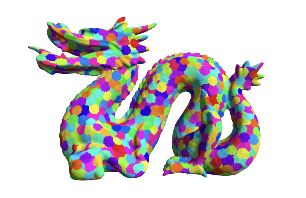
The sample code includes an implementation of meshlet culling using Metal mesh shaders. It uses a pre-meshletized version of the famous Stanford dragon that is chopped up into meshlets, where each triangle is colored to show the meshlet it belongs to. Download it here.
Acknowledgements
Thanks to ChatGPT for writing an early draft of this post.
- In contrast to OpenGL, Metal has not historically had support for programmable geometry amplification, which was a core idea behind geometry shaders. Metal has long had support for fixed-function amplification in the form of tessellation, and more recently with vertex amplification, but object and mesh shaders more fully deliver on the promise of amplification. ↩
- This program is quite limited and brittle and I don’t recommend it for production use. It only supports one mesh per asset, one submesh per mesh, and it has no support for materials. It is for demonstrating the bare minimum use case of meshoptimizer. ↩
- There is a tradeoff to be made between meshlet size and occupancy. This topic is explored here for Nvidia GPUs, but you should experiment and profile with your own content to find a happy medium. ↩
Hi,
Thanks you for this article.
I have a question regarding the Object Shader. What is the maximum number of threadgroups that it can dispatch? What’s the max size allowed for threadgroupsPerGrid?
Thank you
I don’t know what the theoretical or practical upper bound on the number of threadgroups per draw call is. I didn’t hit it in my experiments. I think you’d likely find yourself limited by how many vertices you were pushing through the pipeline before you reasonably encountered it. Imagine launching a compute grid over an 8k^2 texture with a 32x32x1 threadgroup size: you’d need 65k threadgroups in order to run one kernel function call per texel. That’s not something you want to do many times per frame, but neither is it beyond the realm of imagination. If each of those threadgroups was instead producing a mesh, that’s up to 16MM triangles per draw. Not an absolutely insane amount of geometry, granted, but you’d likely want to think about using a BVH or other partitioning strategy long before you reach that point.
Long story short: probably more than you need. If you find yourself hitting the limit, just split your draw call and pass in a “base mesh” index to your object and mesh shaders so you can process your meshes in smaller batches.
Thank you.
I was under the impression that the Object Shader Grid max size was 1024 threadgroups.
Thank you for your clarification. Your article helped me get started with Mesh Shaders.
I was able to run an 8192x1x1 threadgroup grid on my M2 Max MacBook Pro without glitches. Your mileage may vary, but I think this at least indicates that the upper bound isn’t restrictively low.
Thank you.
One final question. I’m going through your code and I noticed that you set threadsPerObjectThreadgroup to 16. Why? Shouldn’t it be 32? Are you doing this to minimize the size of the payload ?
16 was a relic of my early experiments. I think it would be better as 32, and I’ve updated the source accordingly. Thanks for your comments!
Hi Warren,
Sorry to bother you again. I was wondering, do you happen to know if VisionOS supports Mesh Shaders? I was trying to implement a simple project that uses mesh shaders and visionOS and I got an error stating that “Device does not support mesh shaders”.
I wanted to confirm with you in case I did a mistake in my code.
Thank you
I would suppose it does. In the same way that the iOS simulator reports different capabilities than physical devices, I’ve noticed the visionOS simulator claiming not to support features that will surely be supported on the real hardware.
Ah. Thank you so much.
Hi Warren!
if (threadIndex == 0) {outMesh.set_primitive_count(meshlet.triangleCount);
}
I’m trying to understand how we’d always know meshlet.triangleCount is valid. Does MSL guarantee that threadIndex 0 is always the last one to execute?
BTW, the sample code seem to behave oddly on an Intel Mac. I’m suspecting there’s something wrong with the driver.
The triangle count of the meshlet isn’t mutated by the object shader or mesh shader; it comes directly from the (read-only) meshlet buffer. So it’s always safe to read, hazard free.
I’m able to reproduce your issues on an Intel MacBook Pro with Intel UHD Graphics 630 (running macOS Ventura 13.6.1 (22G313)). The issue has to do with the implementation of the SIMDgroup prefix sum and sum functions. I’m not sure of a good workaround, but a possible fix is to unconditionally set
payloadIndextothreadIndexon line 124 and setvisibleMeshletCountto the number of threads per threadgroup (obtainable via a parameter attributed with[[threads_per_threadgroup]]). This will disable culling, but should fix the glitches as well.My mistake. I meant setting of visibleMeshletCount in the Object Shader.
Ah, in that case, we know that the first active thread has the correct visible meshlet count because the call to
simd_sumensures that all threads in the threadgroup have finished executing up to that point, even without explicit synchronization (refer to section 6.9.2 of the Metal Shading Language spec).I have a question related to the depth buffer setup when using mesh shaders.
I saw your example and there doesn’t seem to be anything special with the depth buffer setup, but when I do use a depth buffer, I see triangles appearing both in front and behind… So I wondered whether there is some race condition with the different thread groups writing to the depth buffer simultaneously …
I created a small example where the mesh shader creates some cubes, and those cubes intersect. Without a depth buffer, the cubes overlap each other by some arbitrary write order. But with the depth buffer, I see strange things.
I can’t post images here, but I took a couple of frame captures and I tagged you on Twitter, from @endavid, so you can see what I mean.
Any hint would be appreciated.
Hi Warren,
I want to know is there any method to get the max number of object threadGroup per grid, when I want to render a big ply model on vision pro, I couldn’t get the right result when the same pipeline seems normal on mac. I tried to launch 5630x1x1 object threadGroup, 32x1x1 object thread per group, max 124 triangles per meshlet. I reduce the object group to 500, the fps seems normal.
Forgive my pool English grammar, thanks!
Hi Yushan, I believe this is constrained by the implementation’s “Maximum threadgroups per mesh shader grid” as documented in the Metal Feature Set Tables. As far as I know, there’s no way to get this number programmatically at runtime, but if you can limit yourself to 1024 threads per grid (or query the device’s supported GPU families), that should be safe.
Thanks for this—the article, the clear explanations, the code. They really helped me to learn these new GPU capabilities!