In this article, we will discuss a method for rendering high-fidelity text with Metal. It’s easy to overlook text rendering when thinking about 3D graphics. However, very few games or applications can get by without displaying any text, so it’s important to consider how we can best use the GPU to incorporate text into our Metal apps.
Download the sample code for this post here.
The Structure and Interpretation of Fonts
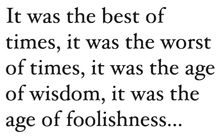
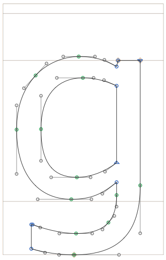
We begin the process of drawing text by selecting a font. Fonts are collections of glyphs, which are the graphical representation of characters or portions of characters. In modern font formats, glyphs are represented as piecewise curves, specifically line segments and quadratic Bezier curves.
Drawing a string of text consists of at least two distinct phases. First, the text layout engine determines which glyphs will be used to represent the string and how they’ll be positioned relative to one another. Then, the rendering engine is responsible for turning the abstract description of the glyphs into text on the screen.
Approaches to Real-Time Text Rendering
There are numerous ways you might go about rendering text on iOS. You are probably familiar with UIKit controls such as UILabel and UITextField. These UI elements are backed by a powerful framework called Core Text. Core Text is a Unicode text layout engine that integrates tightly with Quartz 2D (Core Graphics) to lay out and render text.
Text layout is an enormously complicated subject that must account for different scripts, writing directions, and typographic conventions. We would never want to reinvent this functionality ourselves, so we’ll let Core Text do a lot of the heavy lifting as we settle in on our solution for real-time text rendering.
Let’s take a brief tour through common ways of drawing text in the context of real-time 3D graphics.
Dynamic Rasterization
One of the most flexible approaches to text rendering is dynamic rasterization, in which strings are rasterized on the CPU, and the resulting bitmap is uploaded as a texture to the GPU for drawing. This is the approach taken by libraries such as stb_truetype.
The disadvantage of dynamic rasterization is the computational cost of redrawing the glyphs whenever the text string changes. Even though much of the cost of text rendering occurs in the layout phase, rasterizing glyphs is nontrivial in its demand on the CPU, and there is no extant GPU implementation of font rasterization on iOS. This technique also requires an amount of texture memory proportional to the font size and the length of the string being rendered. Finally, when magnified, rasterized text tends to become blurry or blocky, depending on the magnification filter.
Font Atlases
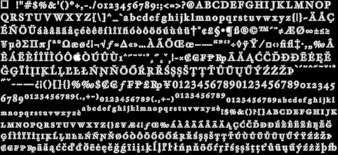
Many applications that use the GPU to draw text prefer to render all possible glyphs up-front rather than drawing them dynamically. This approach trades off texture memory for the computational cost of rasterizing glyphs on-demand. In order to minimize the amount of texture memory required by a font, the glyphs are packed into a single rectangular texture, called an atlas. The figure below illustrates such a texture.
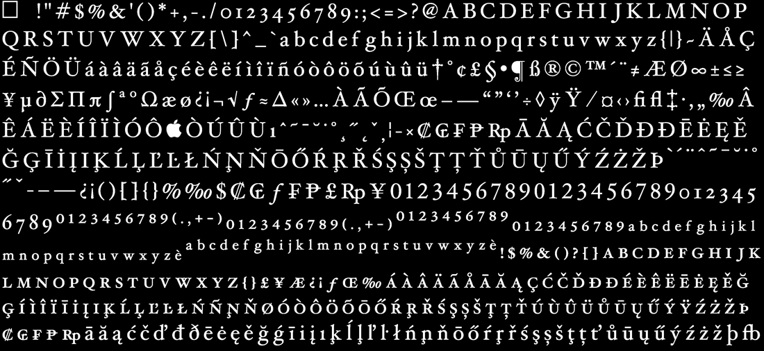
An ancillary data structure stores the texture coordinates describing the bounding rectangle of each glyph. When drawing a string, the application generates a mesh with the appropriate positions and texture coordinates of the string’s constituent glyphs.
One disadvantage of font atlases is that they consume a sizable amount of memory even when many of the glyphs they contain are not used at runtime.
Like dynamic rasterization, text rendered with an atlas texture suffers from a loss of fidelity upon magnification. Here, the problem may be even worse, since the glyphs are often drawn smaller in order to pack an entire font into one texture.
In the next section, we will seek to rectify some of the issues with naïve atlas-based text rendering.
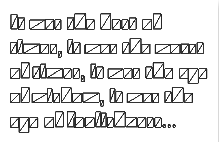
Signed-Distance Fields
The approach we will explore in depth uses a signed-distance field, which is a precomputed representation of a font atlas that stores the glyph outlines implicitly. Specifically, the texel values of a signed-distance field texture correspond to the distance of the texel to the nearest glyph edge, where texels outside the glyph take on negative values.
In order to store a signed-distance field in a texture, it must be scaled and quantized to match the pixel format. Our sample project uses a single-channel 8-bit texture, consuming one byte per pixel. By this construction, texels that fall exactly on the edge of a glyph have a value of 127, or 50%.
In its simplest incarnation, signed-distance field rendering can be done with fixed-function alpha testing. By discarding all fragments whose value is less than 50%, only those pixels inside the glyph will be rendered. Unfortunately, this has the effect of producing “wiggles” along the edges of the glyph, since the downsampled and quantized distance texture does not capture adequate detail to perfectly recreate the ideal outline.
An improvement to the alpha test technique is to use a pixel shader to interpolate between the inside and outside of the glyph, thus smoothing out the wiggly discontinuity. This is described in detail below.
Signed-distance field rendering was brought into the mainstream by Chris Green’s 2007 article describing the use of the technology in Valve’s hit game Team Fortress 2. Our implementation will closely follow the scheme laid out in Green’s paper.
Signed-Distance Field Rendering in Metal
In this section we will describe in detail a method for achieving smooth text rendering on the GPU with Metal.
Generating a Font Atlas Texture
The first step is to render all of the available glyphs in our chosen font into an atlas. For this article, an optimal packing is not used; rather, the glyphs are simply laid out left to right, wrapping lines from top to bottom in a greedy fashion. This simplifies the implementation greatly, at the cost of some wasted space.
The sample code constructs a font atlas from a UIFont by determining the maximum size of the selected font whose glyphs will fit entirely within the bitmap used to construct the atlas (4096×4096 pixels). It then uses Core Text to retrieve the glyph outlines from the font and render them, without antialiasing, into the atlas image.
As the font atlas is being drawn, the implementation also stores the origin and extent (i.e., the texture coordinates) of each glyph in a separate array. This array is used during rendering to map from the laid-out glyphs to their respective area on the atlas texture.
Generating a Signed-Distance Field
The above procedure produces a binary image of the font at a fairly high resolution. That is, pixels that fall inside of a glyph are all the way “on” (255), and pixels that are outside a glyph are all the way “off” (0). We now need to perform a signed-distance transform on this bitmap to produce a signed-distance field representation of the font atlas, which we will use for rendering.
A Brute Force Approach
Generating a signed-distance field entails finding the distance from each texel to the closest glyph edge. Some implementations, such as GLyphy, perform this calculation directly against the piecewise curve representation of the glyphs. This approach can have spectacular fidelity, but the implementation is complicated and fraught with edge cases.
As we have chosen to generate a bitmap representation of the font, we could simply iterate over the neighborhood of each texel, performing a minimizing search as we encounter texels on the other side of the edge. To even approach tractability, this requires that we choose a reasonably-sized area in which to conduct our search.
A reasonable heuristic is half the average stroke width of the font. For example, in a font for which a typical stroke is 20 pixels wide, texels that are so far inside the glyph that they have a distance of greater than 10 are already going to be clamped to the maximum value of “insideness” during rendering. Similarly, texels at a distance of more than 10 outside the glyph are unlikely candidates for influencing the way the glyph is rendered. Therefore, we would conduct a search on the 10 x 10 neighborhood around each texel.
According to Green, the brute-force approach was suitably fast for creating distance fields for text and vector artwork on the class of workstations used in the production of TF2. However, since there has been so much research into signed-distance field generation, let’s take a look at a slightly better approach that will allow us to generate them fairly quickly, even on mobile hardware.
A Better Approach: Dead Reckoning
Signed-distance fields have broad applicability, and have therefore been the subject of much research. G. J. Grevera, building on a venerable algorithm known as the chamfer distance algorithm, constructed a more precise heuristic known as “dead reckoning.” In essence, the algorithm performs two passes over the source image, first propagating the minimal distance down and to the right, then propagating the minimal distances found in the first pass back up and to the left. At each step, the distance value is determined as the minimum distance value over some mask surrounding the center texel, plus the distance along the vector to the nearest previously-discovered edge.
Without going into all the details of this algorithm, it is worth noting that it is drastically faster than the brute-force approach. Across both passes, dead reckoning consults a neighborhood of just 3×3 texels, far fewer than a brute-force algorithm of similar accuracy. Although I have not implemented it with a compute shader, I strongly suspect it could be made faster still with a GPU-based implementation.
Using Core Text for Layout
Once we have the signed-distance field representation of a font, we need a way to transform it into glyphs on the screen. The first part of this process is, again, using the Core Text layout engine to tell us which glyphs should be rendered, and how they should be positioned. We use a CTFramesetter object to lay out the text in a chosen rectangle. The framesetting process produces an array of CTLine objects, each containing series of glyphs.
To construct a text mesh for rendering with Metal, we enumerate the glyphs provided by the Core Text framesetter, which gives us their screen-space coordinates and an index into the table of texture coordinates we constructed earlier when building the font atlas texture. These two pieces of data allow us to create an indexed triangle mesh representing the text string. This mesh can then be rendered in the usual fashion, with a fragment shader doing the heavy lifting of transforming from the signed-distance field texture to an appropriate color for each pixel.
The Orthographic Projection
When drawing text onto the screen, we use an orthographic, or parallel projection. This kind of projection flattens the mesh to the near viewing plane without introducing the foreshortening inherent in a perspective projection.
When rendering UI elements, it is convenient to select an orthographic projection whose extents match the native resolution of the screen. Therefore, the orthographic projection used by the sample application uses (0, 0) as the upper-left corner of the screen and the drawable width and height of the screen, in pixels, as the bottom-right corner, matching UIKit’s convention.
Mathematically, this transformation is represented by the following matrix:

Here  ,
,  ,
,  ,
,  ,
,  , and
, and  are the left, right, top, bottom, near and far clipping plane values. The near and far planes are assumed to sit at
  and
and  , respectively.
The Vertex and Fragment Functions
The vertex function for drawing text is very straightforward; it looks exactly like vertex functions we’ve used in the past. Each vertex of the text mesh is transformed by a model matrix (which can be used to position and scale the text) and a combined view-projection matrix, which is simply the orthographic projection matrix discussed above.
The fragment function, on the other hand, is a little more involved. Since we are using the signed-distance field as more of a look-up table than a texture, we need to transform the sampled texel from the field into a color value that varies based on the proximity of the pixel to the corresponding glyph’s edge.
We apply antialiasing at the edges of the glyphs by interpolating from opaque to translucent in a narrow band around the edge. The width of this band is computed per-pixel by finding the length of the gradient of the distance field using the built-in dfdx and dfdy functions. We then use the smoothstep function, which transitions from 0 to 1 across the width of this smoothed edge, using the sampled distance value itself as the final parameter. This produces an edge band that is roughly one pixel wide, regardless of how much the text is scaled up or down. This refinement on Green’s original approach is due to Gustavson and is explained in detail in his chapter in OpenGL Insights.
Here is the complete fragment function for rendering a glyph from a signed-distance field representation:
float edgeDistance = 0.5;
float dist = texture.sample(samp, vert.texCoords).r;
float edgeWidth = 0.7 * length(float2(dfdx(dist), dfdy(dist)));
float opacity = smoothstep(edgeDistance - edgeWidth, edgeDistance + edgeWidth, dist);
return half4(textColor.r, textColor.g, textColor.b, opacity);
Note that we return a color that has an alpha component, so the pipeline state we use should have alpha blending enabled in order for the text to properly blend with the geometry behind it. This also implies that the text should be drawn after the rest of the scene geometry.
The Sample App
Download the sample code for this post here
The sample project for this post renders a paragraph of text that can be zoomed and panned in real-time. Interactivity is achieved with a pair of UIGestureRecognizers. Notice how the edges of the glyphs remain quite sharp even under extreme magnification, in contrast to the way a pre-rasterized bitmap texture would become jagged or blurry under magnification.
Conclusion
In this post we have considered a handful of ways to draw text with the GPU. We took a deep look at the use of signed-distance fields to increase the fidelity of rendered text while keeping texture memory requirements to a minimum. This technique allows quick generation of font atlases which can then be used to draw text on the GPU extremely fast. Give it a try, and please comment below if you’ve found it useful.
This is very cool, Warren!
I was trying to look at the distance field with the idea of trying the glow effect. I noticed that often the distance field is closely clipped to glyphBounds. I added the following in the buildMeshWithString function…
//———————-
// inflate by 2.0 pixels
//———————-
float heightY = maxY – minY;
if (heightY > 0.0000001)
{
float heightT = maxT – minT;
float bounds_inflation = 2.0;
float info_inflation = bounds_inflation * heightT / heightY;
minY -= bounds_inflation;
maxY += bounds_inflation;
minT -= info_inflation;
maxT += info_inflation;
//———————-
float heightX = maxX – minX;
float heightS = maxS – minS;
info_inflation = bounds_inflation * heightS / heightX;
minX -= bounds_inflation;
maxX += bounds_inflation;
minS -= info_inflation;
maxS += info_inflation;
}
Thanks for the note, Jim. I toyed with the idea of adding padding to avoid clipping, but ultimately didn’t. It’s certainly more evident in some cases than in others. Did you eventually get satisfactory results?
I understand that my hack is not optimal and the 2 pixel inflation is arbitrary. Trying to inflate by more starts to show other clipping issues because of the glyph spacing makes the distance fields start to overlap.
I am suspicious that the close clipping may be affecting your version even though you are not trying to draw the distance field. What do you think?
http://www.nordicsoftware.com/IMG_0371.jpg
Here is a second ipad screen shot after adding my code.
http://www.nordicsoftware.com/IMG_0372.jpg
Great post! Thank you so much for this blog, it is helping me a lot to learn about metal.
I was wondering if you could talk about drawing anti-aliased lines in a future post, and effects like blur/glow.
Thanks
Hey Joe. Not the OP, but this link: http://liu.diva-portal.org/smash/get/diva2:618269/FULLTEXT02.pdf
has the info on glow and a bunch of other effects, using SDF. I was able to make it work after playing a bit with quantize() function from the OP code.
I know a lot of time has passed, but I’m pretty sure people read this post)
Hello
Thanks for posting this article – i found it helpful while working on my signed distance field implementation. Just wanted to add that you can greatly optimise your shader by swapping:
float edgeWidth = 0.7 * length(float2(dfdx(dist), dfdy(dist)));
for:
float edgeWidth = fwidth(distance);
length() will use square root, so is very slow. fwidth() produces the same results for me though i must admit i dont know what is going on inside that function 🙂
Thanks again!
Yep, using
fwidthis definitely a viable performance optimization. It basically computes the sum of the automatic directional derivatives (dfdxanddfdy), the Manhattan distance, rather the hypotenuse. I consciously chose to use the more precise method, but you’re correct that you can save a lot of cycles with the approximation.Thanks for the manhattan distance link – i’ve not heard of that before and im sure it’ll be useful in the future 🙂
I’ve finished my signed distance field font code now, and also wanted to add that if anyone is having trouble with their fonts looking bad at small sizes, try turning on mip-mapping and it will make a huge difference!
Hello,
Thanks for posting the article with working example. It helps a lot. I have a problem further, I am trying to overlay some text over my video texture. I have two textures fetched from drawable of same UIView. How can I draw both textures in a way text overlays video ?
Thanks
Sagar
It sounds like you want to blend text on top of video content. This tutorial doesn’t cover alpha blending, but I think you could use the same approach as detailed here to generate an alpha value suitable for blending. Basically, you’d render or acquire the video data as a texture, then draw the text last, calculating the alpha value for the text mesh according to the same
smoothstepfalloff that’s used to antialias the edges. You’d also need to enable blending on your render pipeline state and set the appropriate blend factors and operations for source-over compositing (basically, the operation should be Add, and the factors should be SourceAlpha for the source RGB/A and OneMinusSourceAlpha for the destination RGB/A). Consult the alpha blending article on this site for more detail.Hi Warren,
I owe 100% of my knowledge of Metal to you and your book. Great work and thank you!
I have a similar problem as described above blending text on top of video. Only in my case it is on top of a sky/spherical galaxy texture.
I got as far as combing your signed-text code with the alpha blending code, generating an alpha value and discarding the fragment . But i have never been successful in displaying the ortho projected text on to a perspective projection (as in alpha blend)
There is a step i am missing and i don’t know what that is. I’ll be lucky to hear from you if you’re still responding to posts here.
thanks
Paul
Thanks for this! 🙂
I ported the code to Swift but I’m having performance and memory issues. The main algorithm takes 40 seconds, while the Objective-C version takes a couple of seconds. I profiled it and it seems to be the time accessing the arrays.
Also, your program uses ~10MB for a 4096 base texture but mine uses 75MB for a 2048 base texture (if I use 4096 it runs out of memory).
The last problem is that when I try to cache the atlas to disc, memory usage increases very rapidly and the app is terminated before it can save anything.
I guess the data types aren’t ideal… I might have overestimated the goodness of Swift….
I left a gist here with the description of the data and the main function,
https://gist.github.com/endavid/e8fab458d668f35d7227548b7d078570
Have you tried profiling the app in Instruments and seeing where it’s spending its time? I wouldn’t expect Swift to be faster on this task, but I’m surprised it takes 10x the time and 7x the memory. If you can share a compilable copy of the project, I’d be interested in taking a look at it.
Hello 🙂 Yes, I was using Instruments. If I’m profiling correctly, it seems it’s just accessing the data in the array what takes so long, that’s why I suspected the data structure… I also had some closures that did the same your preprocessor macros did, but I was a bit paranoid that those closures were the cause of the slow-down so I removed them. Performance didn’t improve.
I’ve put the project here: https://github.com/endavid/VidEngine/tree/textprimitive-fail
Excuses it’s a bit big. I’ve tagged a commit with “textprimitive-fail”. If you run that, you should see this (after a 40 sec wait on an iPhone6),
https://www.dropbox.com/s/uy5kh0z5csu75uj/Screen%20Shot%202017-05-29%20at%2013.30.01.png?dl=0
Perhaps instead of a [Float] I should use a MTLBuffer directly… That way I could even try doing the computation in the GPU.
Thanks for checking!! 🙂
I’ve ended up switching Swift arrays for native arrays and I managed to make the code more than 5 times faster with just that change. Here’s the updated project,
https://github.com/endavid/VidEngine/tree/fontatlas-array-optimization
I’ve started a discussion in Stackoverflow as well, https://stackoverflow.com/q/45045811/1765629
Cheers
Thanks for introducing distance field to me. It is very interesting. One thing I couldn’t find clear explanation either in your post or Gustavson’s chapter is the edgeWidth calculation. Why is 0.75 * length(float2(dfdx(sampleDistance), dfdy(sampleDistance))) a good estimation of edge width? What’s the math theory behind it?
According to Gustavson,
In other words, it has the effect of widening the aperture of the edge, making it softer at the expense of making it blurrier. There’s no formula for the leading factor; it’s a tunable parameter that allows you to select between a wavier or blurrier outline.
I’m hoping to learn more about text rendering in Metal and found your example. I realize this comes very late, but how would I change the font? If I change the string from Hoefler, the program crashes with a null access, I think. Is there a list of valid strings, or is there something else that I need to do? Thanks for your time.
Sorry to bring up an OLD post, but this is one of the few posts about this on the Internet still! So I ported this to Mac using NSFont and the like, and on a Retina screen, everything is fine! But when displayed at small (11pt) font sizes on a non retina screen, the characters lose portions of themselves.
See: http://www.downstairsgeek.com/retina.png http://www.downstairsgeek.com/nonretina.png
Literally the only change in settings is to move the window to monitor where the backing store scale is 1 vs 2, all other settings are identical.. I know enough to draw the rest of my app, which is ALL 2d lines & polygons, which all work fine in either mode, just the text is borked. Is there an easy solution for a non-retina screen here, or am I just hosed?
I tried to compile the source in Xcode but I get errors. This is 2022 with latest OS.
Please provide the specific error messages you received, along with the actual version numbers of your Xcode and OS.
I have uploaded a new version of the project that modernizes the sample somewhat, and should run correctly on current iOS.
HI. How to make the edges smoother. Artifacts visible when zooming
SDFs are not without their pitfalls. They hold up under modest magnification, but rounded-off corners and undulating edges are an inevitable consequence of this kind of naive SDF glyph rendering implementation. For better reconstruction, you could look into newer work on multichannel SDFs, use a non-SDF atlas-based approach like those found in imgui or NanoVG, or use a robust, off-the-shelf product like Slug.
If I could figure the mystery of MSFT Direct2D implementation on 3D contexts, I would be happy.
What I would like is something like D2D for Android native side C++ software.
All I want is that such library that must use NDK hosted 3D libraries (OGL etc), is not to screw up anything just because it is using 3D.
D2D is perfect. Nobody knows what they are doing there. How do they draw text and round shapes?
In particular, I want to know if what they do there is REAL acceleration for text or maybe text is not accelerated at all, because it is totally rendered on CPU which is the natural way as far as I think about text, Warren. Metal is for games.
Developers are not expected to create their own D2D for some ratched platform like Android that do not offer anything native side and everything JAVA side, that in fact calls native side for SKIA on 3D. For me, Android is a Linux. I have zero interest in the JAVA side.
How do I set the text in a free-form direction, such as vertical from left to right
Core Text is quite flexible when it comes to layout. For right-to-left languages, it automatically lays out in the appropriate direction according to embedded RTL marks. For Asian languages, you can use Ruby annotations and vertical glyph forms to get decent vertical layout. For baseline-oriented writing systems, you can use Core Text in concert with other frameworks to lay out glyphs along an arbitrary path. The reason I suggest sticking with Core Text is that there’s a deep interplay between layout and glyph selection, and trying to roll your own layout engine is a very complex exercise. Even if you have to resort to just asking Core Text to perform layout and then use its structures to do some of the layout and rendering yourself, that’s better than doing it all from scratch, in my opinion.