Textures are a central topic in rendering. Although they have many uses, one of their primary purposes is to provide a greater level of detail to surfaces than can be achieved with vertex colors alone.
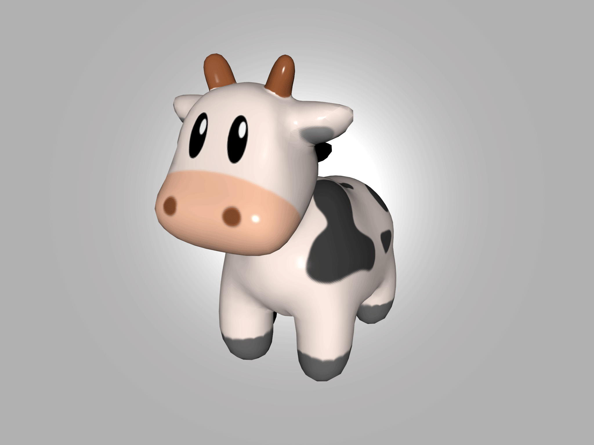
In this post, we’ll talk about texture mapping, which helps us bring virtual characters to life. We’ll also introduce samplers, which give us powerful control over how texture data is interpreted while drawing. Along the way, we will be assisted by a cartoon cow named Spot.
You can download the sample code for this post here.
Textures
Textures are formatted image data. This makes them distinct from buffers, which are unstructured blocks of memory. The types of textures we will be working with in this post are 2D images. Although Metal supports several other kinds of textures, we can introduce almost all of the important concepts by walking through an example of texture mapping.
Texture Mapping
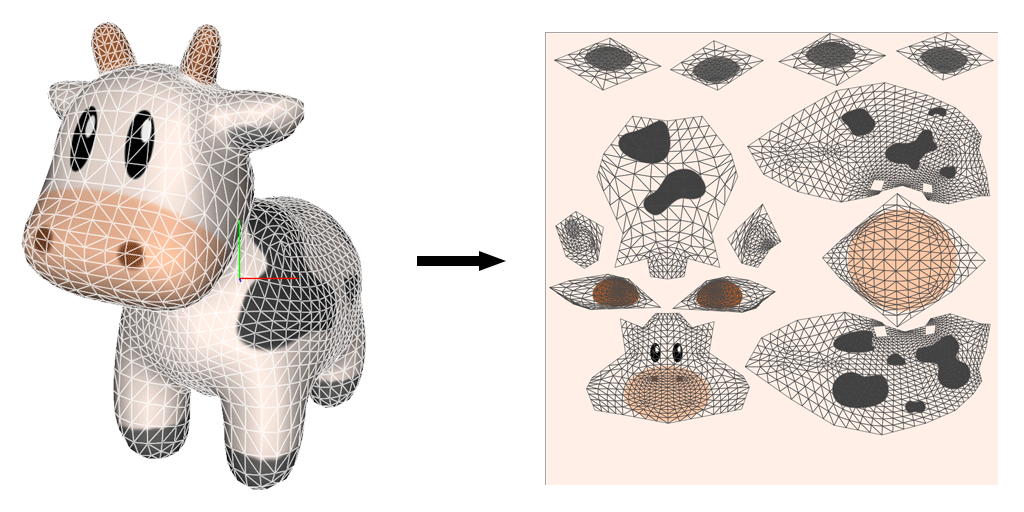
Texture mapping is the process of associating each vertex in a mesh with a point in a texture. This is similar to wrapping a present, in that a 2D sheet of wrapping paper (a texture) is made to conform to a 3D present (the mesh).
Texture mapping is usually done with a specialized editing tool. The mesh is unwrapped into a planar graph (a 2D figure that maintains as much of the connectivity of the 3D model as possible), which is then overlaid on the texture image.
The following figure shows a 3D model of a cow (with the edges of its constituent faces highlighted) and its corresponding texture map. Notice that the various parts of the cow (head, torso, legs, horns) have been separated on the map even though they are connected on the 3D model.
Coordinate Systems
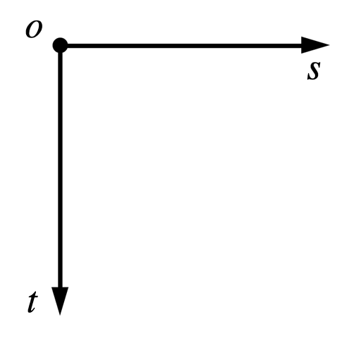
In Metal, the origin of the pixel coordinate system of a texture coincides with its top left corner. This is the same as the coordinate system in UIKit. However, it differs from the default texture coordinate system in OpenGL, where the origin is the bottom left corner.
The axes of the texture coordinate system are often labeled s and t (or u and v) to distinguish them from the x and y axes of the world coordinate system.
The coordinate system of the texture coordinates must agree with the coordinate system of the image data. Some 3D modeling applications and 3D model formats assume that the texture coordinate origin is in the bottom left of the image, causing the texture to be applied upside-down at runtime. This can be solved either when the image is written (by storing the image “flipped”), or when the image is read, by flipping the image data vertically before it is copied into the texture. It can also be corrected in shader code by subtracting the y coordinate of the texture coordinates from 1 before sampling.
The sample code chooses to flip images when loading. The image utilities from UIKit are used to load the image, which is then transformed into the Metal texture coordinate system by drawing it into a “flipped” context. The code for this is shown in a later section.
Pixel Coordinates Versus Normalized Coordinates
Metal is flexible enough to allow us to specify texture coordinates in pixel coordinates or normalized coordinates. Pixel coordinates range from (0, 0) to (width – 1, height – 1). They therefore depend on the dimensions of the texture image. Normalized coordinates range from (0, 0) to (1, 1), which makes them independent of image size.
I have chosen to use normalized coordinates throughout this post.
Filtering
Textures are discrete images composed of a finite number of pixels (called texels). However, when drawing, a texture may be drawn at a resolution that is higher or lower than its native size. Therefore, it is important to be able to determine what the color of a texture should be between its texels, or when many texels are crunched into the same space. When a texture is being drawn at a size higher than its native size, this is called magnification. The inverse process, where a texture is drawn below its native resolution, is called minification.
The process of reconstructing image data from a texture is called filtering. Metal offers two different filtering modes: nearest and linear.
Nearest (also called “nearest-neighbor”) filtering simply selects the closest texel to the requested texture coordinate. This has the advantage of being very fast, but it can cause the rendered image to appear blocky when textures are magnified (i.e., when each texel covers multiple pixels).
Linear filtering selects the four nearest texels and produces a weighted average according to the distance from the sampled coordinate to the texels. Linear filtering produces much more visually-pleasing results than nearest-neighbor filtering and is sufficiently fast to be performed in real-time.
Mipmaps
When a texture is minified, multiple texels may coincide with a single pixel. Even slight motion in the scene can cause a shimmering phenomenon to appear. Linear filtering does not help the situation, as the set of texels covering each pixel changes from frame to frame.
One way to abate this issue is to prefilter the texture image into a sequence of images, called mipmaps. Each mipmap in a sequence is half the size of the previous image, down to a size of 1×1. When a texture is being minified, the mipmap at the closest resolution is substituted for the original texture image.
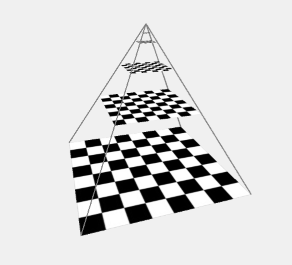
The name “mipmap” comes from the Latin phrase multum in parvo, which roughly means “much in little”.
Although it is possible to build your own mipmap sequence manually, Metal can do this for you when creating a texture. The texture2DDescriptorWithPixelFormat:width:height:mipmapped: convenience method (which we will use later) will calculate the number of mipmap levels necessary and assign it to the texture descriptor it returns. Otherwise, you are obligated to set the mipmapLevelCount property to the appropriate value, which happens to be  .
.
The sample code does not demonstrate the use of mipmapping.
Addressing
The following discussion is framed in terms of normalized coordinates. If you prefer pixel coordinates, simply replace “1” with “width” or “height” where appropriate.
Typically, when associating texture coordinates with the vertices of a mesh, the values are constrained to [0, 1] along both axes. However, this is not always the case. Negative texture coordinates, or coordinates greater than 1 can also be used. When coordinates outside the [0, 1] range are used, the addressing mode of the sampler comes into effect. There are a variety of different behaviors that can be selected.
Clamp-to-Edge Addressing
In clamp-to-edge addressing, the value along the edge of the texture is repeated for out-of-bounds values.
Clamp-to-Zero Addressing
In clamp-to-zero addressing, the sampled value for out-of-bounds coordinates is either black or clear, depending on whether the texture has an alpha color component.
Repeat Addressing
In repeat addressing, out-of-bounds coordinates wrap around the corresponding edge of the texture and repeat from zero. In other words, the sampled coordinates are the fractional parts of the input coordinates, ignoring the integer parts.
Mirrored Repeat Addressing
In mirrored repeat addressing, the sampled coordinates first increase from 0 to 1, then decrease back to 0, and so on. This causes the texture to be flipped and repeated across every other integer boundary.
Creating Textures in Metal
Before we actually ask Metal to create a texture object, we need to know a little more about pixel formats, as well as how to get texture data into memory.
Pixel Formats
A pixel format describes the way color information is laid out in memory. There are a few different aspects to this information: the color components, the color component ordering, the color component size, and the presence or absence of compression.
The common color components are red, green, blue, and alpha (transparency). These may all be present (as in an RGBA format), or one or more may be absent. In the case of a fully-opaque image, alpha information is omitted.
Color component ordering refers to which color components appear in memory: BGRA or RGBA.
Colors may be represented with any degree of precision, but two popular choices are 8 bits per component and 32 bits per component. Most commonly, when 8 bits are used, each component is an unsigned 8-bit integer, a value between 0 and 255. When 32 bits are used, each component is usually a 32-bit float ranging from 0.0 to 1.0. Obviously, 32 bits offer far greater precision than 8 bits, but 8 bits is usually sufficient for capturing the perceivable differences between colors, and is much better from a memory standpoint.
The pixel formats supported by Metal are listed in the MTLPixelFormat enumeration.
Loading Image Data
We will use the powerful utilities provided by UIKit to load images from the application bundle. To create a UIImage instance from an image in the bundle, we only need one line of code:
UIImage *image = [UIImage imageNamed:textureName];
Unfortunately, UIKit does not provide a way to access the underlying bits of a UIImage. Instead, we have to draw the image into a Core Graphics bitmap context that has the same format as our desired texture. As part of this process, we transform the context (with a translation followed by a scale) such that the result image bits are flipped vertically. This causes the coordinate space of our image to agree with Metal’s texture coordinate space.
CGImageRef imageRef = [image CGImage];

// Create a suitable bitmap context for extracting the bits of the image
NSUInteger width = CGImageGetWidth(imageRef);
NSUInteger height = CGImageGetHeight(imageRef);
CGColorSpaceRef colorSpace = CGColorSpaceCreateDeviceRGB();
uint8_t *rawData = (uint8_t *)calloc(height * width * 4, sizeof(uint8_t));
NSUInteger bytesPerPixel = 4;
NSUInteger bytesPerRow = bytesPerPixel * width;
NSUInteger bitsPerComponent = 8;
CGContextRef context = CGBitmapContextCreate(rawData, width, height,
                                             bitsPerComponent, bytesPerRow, colorSpace,
                                             kCGImageAlphaPremultipliedLast | kCGBitmapByteOrder32Big);
CGColorSpaceRelease(colorSpace);

// Flip the context so the positive Y axis points down
CGContextTranslateCTM(context, 0, height);
CGContextScaleCTM(context, 1, -1);

CGContextDrawImage(context, CGRectMake(0, 0, width, height), imageRef);
CGContextRelease(context);
Texture Descriptors
A texture descriptor is a lightweight object that specifies the dimensions and format of a texture. When creating a texture, you provide a texture descriptor and receive an object that conforms to the MTLTexture protocol, which is a subprotocol of MTLResource. The properties specified on the texture descriptor (texture type, dimensions, and format) are immutable once the texture has been created, but you can still update the content of the texture as long as the pixel format of the new data matches the pixel format of the receiving texture.
The MTLTextureDescriptor class provides a couple of factory methods for building common texture types. To describe a 2D texture, you must specify the pixel format, texture dimensions in pixels, and whether Metal should allocate space to store the appropriate mipmap levels for the texture.
[MTLTextureDescriptor texture2DDescriptorWithPixelFormat:MTLPixelFormatRGBA8Unorm
                                                   width:width
                                                  height:height
                                               mipmapped:YES];
Creating a Texture Object
It is now quite straightforward to create a texture object. We simply request a texture from the device by supplying a valid texture descriptor:
id<MTLTexture> texture = [self.device newTextureWithDescriptor:textureDescriptor];
Updating Texture Contents
Setting the data in the texture is also quite simple. We create a MTLRegion that represents the entire texture and then tell the texture to replace that region with the raw image bits we previously retrieved from the context:
MTLRegion region = MTLRegionMake2D(0, 0, width, height);
[texture replaceRegion:region mipmapLevel:0 withBytes:rawData bytesPerRow:bytesPerRow];
Passing Textures to Shader Functions
This texture is now ready to be used in a shader. To pass a texture to a shader function, we set it on our command encoder right before we issue our draw call:
[commandEncoder setFragmentTexture:texture atIndex:0];
This texture can now be referred to by index with the attribute [[texture(0)]] in a shader function’s parameter list.
Samplers
In Metal, a sampler is an object that encapsulates the various render states associated with reading textures: coordinate system, addressing mode, and filtering. It is possible to create samplers in shader functions or in application code. We will discuss each in turn in the following sections.
Creating Samplers in Shaders
We will use samplers in our fragment function, because we want to produce a different color for each pixel in the rendered image. So, it sometimes makes sense to create samplers directly inside a fragment function.
The following code creates a sampler that will sample in the normalized coordinate space, using the repeat addressing mode, with linear filtering:
constexpr sampler s(coord::normalized,
                    address::repeat,
                    filter::linear);
Samplers that are local to a shading function must be qualified with constexpr. This keyword, new in C++11, signifies that an expression may be computed at compile-time rather than runtime. This means that just one sampler struct will be created for use across all invocations of the function.
The coord value may either be normalized or pixel.
The possible values for address are clamp_to_zero, clamp_to_edge, repeat, mirrored_repeat.
The possible values for filter are nearest and linear`, to select between nearest-neighbor and linear filtering.
All of these values belong to strongly-typed enumerations. Strongly typed enumerations are a new feature in C++11 that allow stricter type-checking of enumerated values. It is an error to omit the type name of the value (i.e., you must say filter::linear and not simply linear).
The parameters may be specified in any order, since the constructor of the sampler is implemented as a variadic template function (another new feature of C++11).
Using a Sampler
Getting a color from a sampler is straightforward. Textures have a sample function that takes a sampler and a set of texture coordinates, returning a color. In a shader function, we call this function, passing in a sampler and the (interpolated) texture coordinates of the current vertex.
float4 sampledColor = texture.sample(sampler, vertex.textureCoords);
The sampled color may then be used in whatever further computation you want, such as lighting.
Creating Samplers in Application Code
To create a sampler in application code, we fill out a MTLSamplerDescriptor object and the ask the device to give us a sampler (of type id<MTLSamplerState>)
MTLSamplerDescriptor *samplerDescriptor = [MTLSamplerDescriptor new];
samplerDescriptor.minFilter = MTLSamplerMinMagFilterNearest;
samplerDescriptor.magFilter = MTLSamplerMinMagFilterLinear;
samplerDescriptor.sAddressMode = MTLSamplerAddressModeRepeat;
samplerDescriptor.tAddressMode = MTLSamplerAddressModeRepeat;

sampler = [device newSamplerStateWithDescriptor:samplerDescriptor];
Note that we had to individually specify the magnification and minification filters. When creating samplers in shader code, we used the filter parameter to specify both at once, but we could also use mag_filter and min_filter separately to get the same behavior as above.
Similarly, the address mode must be set separately for each texture axis, whereas we did this with the sole address parameter in shader code.
Passing Samplers as Shader Arguments
Passing samplers looks very similar to passing textures, but samplers reside in a different set of argument table slots, so we use a different method to bind them:
[commandEncoder setFragmentSamplerState:sampler atIndex:0];
We can now refer to this sampler by attributing it with [[sampler(0)]] in shader code.
The Sample Project
The sample code for this post borrows heavily from the earlier post on lighting and rendering in 3D, so the shared concepts are not explained in this post.
The major change is the use of a texture/sampler pair to determine the diffuse color of the mesh at each pixel instead of interpolating a single color across the whole surface. This allows us to draw our textured cow model, producing a greater sense of realism and detail in the scene.
You can download the sample project here. If you run it on a Metal-enabled device, you can spin Spot around in 3D to show off those specular highlights. Be careful, though: if you spin her too fast, you might hear her moo in protest…
Hello. I’m confused about the index buffer again. Looking at the flattened UV map of the cow, each vertex should have a unique UV coordinate, no? Because each UV is unique and each UV is associated with a vertex, doesn’t that make the vertex unique also? Also Apple OpenGL best practice say use interleaved buffer
http://tiny.cc/working-with-vertex-data [Ed: link shortened to fix formatting issue]
Does same rule still apply in Metal?
Each vertex in the cow mesh has a unique set of texture coordinates, yes. If that were not the case, and two faces had different texture coordinates for the same vertex position, you would get discontinuities in the texture mapping, potentially causing abrupt visual artifacts. The OBJ format makes no assumption that vertex positions and texture coordinates have such a 1-to-1 mapping, so the code has to do extra work to ensure that it associates each position with its corresponding (unique) texture coordinates.
Regarding interleaved formats, I’ve heard from Apple engineers that they are still preferred over disparate buffers. The reason is cache coherency. If your vertex data is spread across several buffers, they are less likely to fit in the cache than if you stream all of the vertex attributes in adjacent memory locations, as described in your link.
Pingback: iOS 8 Metal Tutorial with Swift Part 3: Adding Texture - Ray Wenderlich
Hi warrenm,
Great tutorials about Metal and its usage. It helps me a lot.
Could you please tell how to use .mtl file along with .obj file.
Broadly speaking, MTL files contain a description of material properties of objects. They are associated with meshes in an OBJ file by including the name of the MTL file in a
mtllibdirective and then referring to the materials it contains by name with ausemtlstatement. The various reflectivity properties of a material (ambient, diffuse, specular, etc) can be specified as colors or as texture maps, and materials also incorporate factors such as index of refraction. You basically need to parse these files and then send the various material properties as parameters (in a buffer) to your fragment shader. Of course, you’ll also need to have a fragment shader that implements a lighting model that supports whatever material properties you want to account for. As a first step, you could start by just parsing the Ka, Kd, Ks factors of each material and using them with a straightforward Blinn-Phong shader, then get more sophisticated from there.Hello. Please, tell me how to use repeat in mtl-file.
I write:
map_Kd -blendv off -blendu off texture.jpg
or
map_Kd -blendv on -blendu on texture.jpg
but I see black color and no texture.
Thanks
I actually don’t know much about the .mtl format, and the sample code doesn’t actually support .mtl files. If you’re using a renderer that does support .mtl loading, try the -clamp off option rather than -blendu and -blendv. In theory, if clamping is disabled, the texture should repeat. But again, this only works if the loader and renderer are written in such a way that this configuration is supported.
Hi ,
Thanks a lot for these tutorials,
i was just try to follow this tutorial but with change in the displayed object but when i tried to change the Object it showed like a block.
i can understand if the object didn’t fully display or any thing like this but it didn’t have any features just a block.
can you please help me with this?
What kind of model are you trying to draw? It’s possible that the scale of the model is inappropriate for the transforms hard-coded in the sample app. Ideally, models should fit in a unit cube about the origin. Happy to look into this further if you can share the model or describe it in more detail.
Thanks a lot for being willing to help me i really appreciate that,
Please find this link for the object i used, https://www.dropbox.com/s/1oa1erugxi0gct4/Ankle.obj.zip?dl=0
it’s an object for CT images of ankle, exported from osirix application and then UV mapping applied by blender .
I suspect one cause for your difficulty is that your model contains about 294,000 triangles, while the sample code supports only up to about 21,800. This limitation exists because I chose to use 16-bit indices for indexing the meshes. If you adapt the code to use 32-bit indices (by modifying the
IndexTypetypedef to be an unsigned 32-bit integer and fixing up all the other places I assumed 16 bit indices), it may well work immediately. My comment from earlier applies as well; your model has bounds that are much larger than a unit cube, so you’ll either need to modify the mesh in an editor or apply a suitable scale factor to the model matrix if you want to use this code to render it.You Sir deserve a medal , thanks a lot for helping me it worked perfectly.
How to tell metal to use the Pixel Coordinates for texture?
If you’re using an
MTLSamplerState, you can set thenormalizedCoordinatesproperty on the descriptor toNO/falseto tell Metal to interpret your texture coordinates as pixel coordinates. If you’re using aconstexprsampler, you can passcoord::pixelas one of its template parameters to do the same.Instead of using an UIImage, it may be easier in many situations to just use the MTKTextureLoader, isn’t it?
https://developer.apple.com/reference/metalkit/mtktextureloader/1535963-newtexture
Certainly, and if it had existed at the time, I would have used it 🙂
What would be a good and efficient procedure of doing a texture to texture blit?
Could you explain how one would go about that?
I am interested in retaining the drawable content to an off screen buffer, and copy it back to the drawable before presentation.
Many thanks for all the great info
Hi Warren,
Thanks for this tutorial, very helpful.
I am trying to write a simple metal code to sample texture. But my texture goes haywire on my final image.(https://github.com/openglGfx/Metal).
Another issue I am having is I am unable to use GPU Frame capture on this project. could you please help me here?
A few things I observed:
(1) Don’t create a command queue every frame. It messes with frame capture and is generally a bad idea. Add a property to your view subclass that holds a reference to a command queue that lives for the duration of your app.
(2) Same with textures and sampler states. They’re expensive objects, so cache them unless they have to change.
(3) In Swift, you should generally favor MemoryLayout.stride over MemoryLayout.size. The former accounts for the fact that vector_float4 is 16 byte aligned and that your vertices are therefore spaced at 48 byte offsets, not 40 byte offsets.
Thanks Warren. That helps a lot.
Appreciate your help.
Hi Warren!
I have been trawling the net daily for a good tutorial using the most current swift version to get a 2d texture to screen; your tutorials seem to be the most concise, whilst also covering best practices… (WWDC! Awesome!)
Any chance you could summarise the required amendments to the current boxed metal game template in Xcode, i.e. to get a texture mapped to the bouncing triangle?
I think one thing is not quite true / clear: specifying coord::pixel will make the coordinates range from (0, 0) to (width, height) and not (0, 0) to (width – 1, height – 1)
With (0, 0) being the top left corner, (0.5, 0.5) the top left pixel and (width, height) the bottom right corner…
Can these newTextureWithDescriptor methods be called on device from multiple threads? In general to what extent is ‘device’ thread safe?
In this thread https://developer.apple.com/forums/thread/93346 someone says:
“You should be able to safely alloc resources from a device. What are you seeing that suggests otherwise?”
I do this and haven’t seen any issues so far but would like to be sure whether its shear luck or defined behaviour.
Yes, the resource creation methods on
MTLDeviceare thread-safe. You still have to carefully manage when you update the contents of resources (I.e., to avoid writing to them when they’re being used by the GPU), but generally speaking it’s safe to create resources on multiple threads.