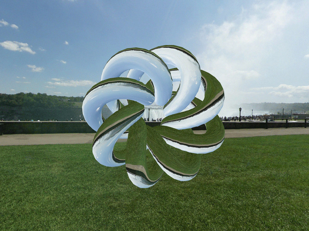
In this post, we’ll talk about some of the more advanced features of texturing in Metal. We’ll apply a cube map to a skybox to simulate a detailed environment surrounding the scene. We’ll also introduce a technique called cubic environment mapping to simulate reflection and refraction, to further enhance the realism of our virtual world.
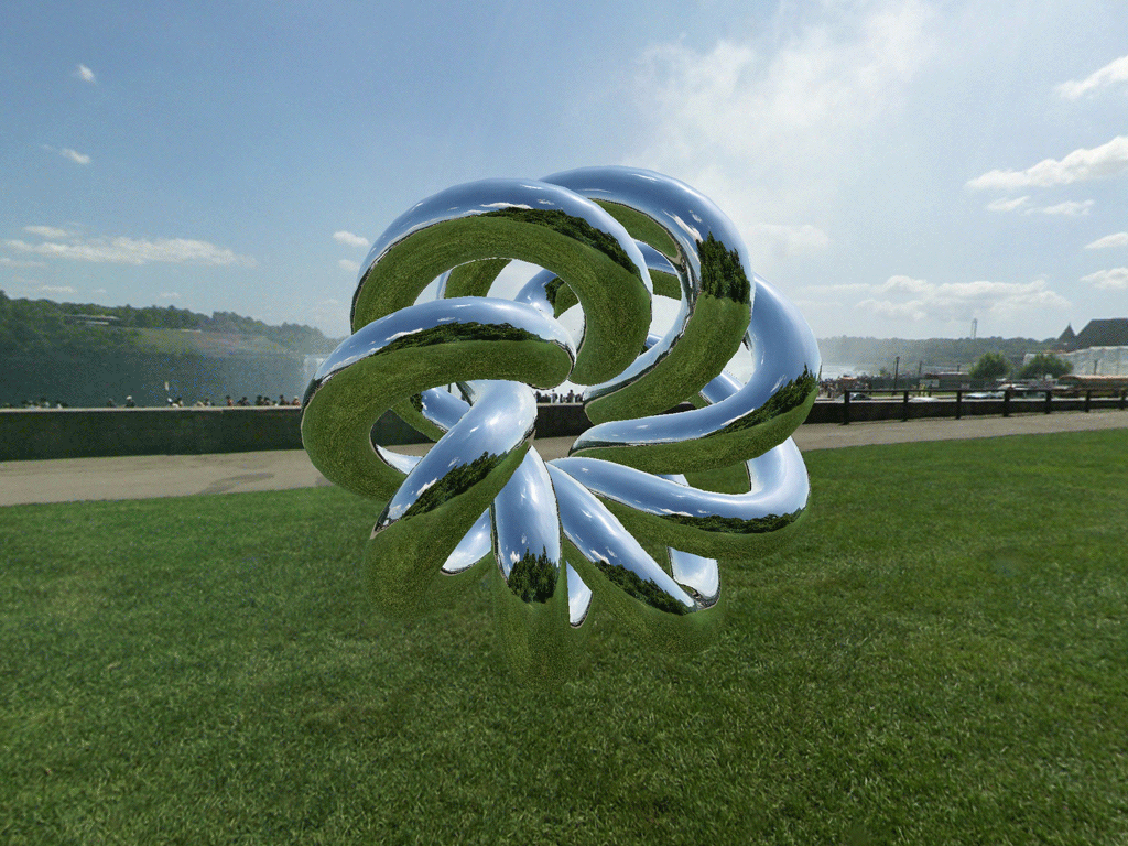
You can download the sample code for this post here. Tapping the screen will switch from reflection mapping to refraction mapping, to demonstrate each of the feature’s we’ll discuss below.
First, let’s talk about the sample scene.
Setting the Scene
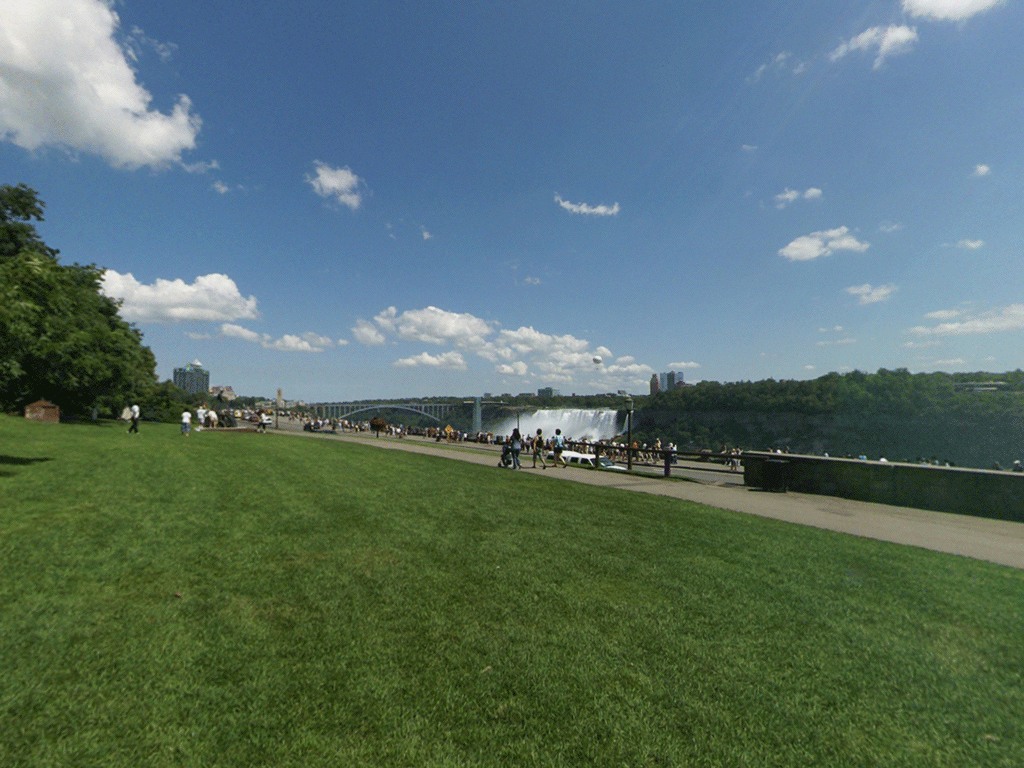
The scene for the sample app consists of a skybox surrounding a torus knot.
Instead of loading models from disk to construct the sample scene, we will be generating the necessary geometry procedurally.
The Vertex Format
Although the objects in our scene will be textured, we do not need to explicitly store texture coordinates in our vertices. Instead, we will generate texture coordinates for the skybox and torus knot in specially-crafted vertex shaders. Therefore, each vertex has only two properties: position and normal:
typedef struct
{
    vector_float4 position;
    vector_float4 normal;
} Vertex;
The Mesh Class
As we’ve done in the past, we use a mesh object to wrap up a vertex buffer and an index buffer so that we can conveniently issue indexed draw calls. The base class, MBEMesh, provides an abstract interface to these two buffers.
The Skybox Mesh
Generating the skybox mesh is straightforward. The skybox is a unit cube about the origin, so the skybox class uses a static list of positions, normals, and indices to build its buffers. Note that the indices are ordered to produce cube faces that point inward, since the virtual camera will be inside the skybox at all times.
The Torus Knot Mesh
The central object in the scene is a torus knot. You are probably familiar with the torus, a geometric figure that consists of a circle swept perpendicularly around another circle.
A torus knot introduces an additional complication by twisting the path taken by the orbiting circle, creating a figure that is more visually interesting:
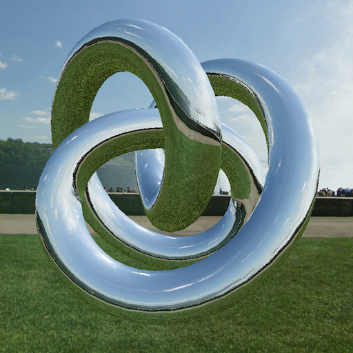
The MBETorusKnotMesh class generates vertices as it sweeps along the path of a torus knot, then generates indices that knit together the vertices into a solid mesh. You can produce a large variety of interesting knots by varying the parameters passed to the mesh’s initializer method. View some other possible shapes here.
Now that we have some geometry to render, let’s talk about a new kind of texture in Metal.
Cube Textures
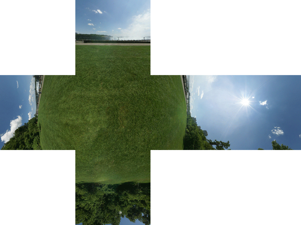
Cube textures (also called “cube maps”) are a special type of texture. In contrast to regular 2D textures, cube textures are collections of six textures that have a spatial relationship to one another. In particular, each image corresponds to a direction along one of the axes of the 3D coordinate system.
In the figure below, the six textures comprising a cube map are laid out to show the cube from the inside. The -Y face is in the middle of the cross.
The Cube Map Coordinate Space
Cube maps in Metal are left-handed, meaning that if you imagine yourself inside the cube, with the +X face to your right, and the +Y face above you, the +Z axis will be the one directly ahead. If instead you are positioned outside the cube, the coordinate system appears to be right-handed, and all of the images are mirrored.
Creating and Loading a Cube Map Texture
Creating a cube texture and loading it with image data is similar to creating and loading a 2D texture, with a couple of exceptions.
The first difference is the texture type. MTLTextureDescriptor has a convenience method for creating a texture descriptor describing a cube texture. The textureType property of the descriptor is set to MTLTextureTypeCube, and the height and width properties are set equal to the size parameter. The width and height of all constituent textures of the cube texture must be equal.
[MTLTextureDescriptor textureCubeDescriptorWithPixelFormat:MTLPixelFormatRGBA8Unorm
                                                      size:cubeSize
                                                 mipmapped:NO];
Creating the texture object from the descriptor is done in the same manner as when creating a 2D texture:
id<MTLTexture> texture = [device newTextureWithDescriptor:textureDescriptor];
The other difference between 2D textures and cube textures is how image data is loaded. Because a cube texture actually contains six distinct images, we have to specify a slice parameter when setting the pixel data for each face. Each slice corresponds to one cube face, with the following mapping:
| Face number | Cube texture face |
|---|---|
| 0 | Positive X |
| 1 | Negative X |
| 2 | Positive Y |
| 3 | Negative Y |
| 4 | Positive Z |
| 5 | Negative Z |
To load the data into every cube face, we iterate over the slices, replacing the slice’s entire region with the appropriate image data:
for (int slice = 0; slice < 6; ++slice)
{
    // ...
    // fetch image data for current cube face
    // ...

    [texture replaceRegion:region
               mipmapLevel:0
                     slice:slice
                 withBytes:imageData
               bytesPerRow:bytesPerRow
             bytesPerImage:bytesPerImage];
}
imageData must be in whatever pixel format was specified in the texture descriptor. bytesPerRow is the width of the cube multiplied by the number of bytes per pixel. bytesPerImage, in turn, is the number of bytes per row multiplied by the height of the cube. Since the width and height are equal, you can substitute the cube side length in these calculations.
Sampling a Cube Map
Cube map texture coordinates work somewhat differently than 2D texture coordinates. The first difference is that three coordinates are required to sample a cube map, rather than two. The three coordinates are treated as a ray originating at the center of the cube, intersecting the face at a particular point on the cube. In this way, cube texture coordinates represent a direction rather than a particular point.
Some interesting edge cases can arise when sampling in this way. For example, the three vertices of a triangle might span the corner of the cube map, sampling three different faces. Metal handles such cases automatically by correctly interpolating among the samples along the edges and corners of the cube.
Applications of Cube Maps
Now that we know how to create, load, and sample a cube map, let’s talk about some of the interesting effects we can achieve with cube maps. First, we need to texture our skybox.
Texturing the Skybox
Recall that we created our skybox mesh from a set of static data representing a unit cube about the origin. The positions of the corners of a unit cube correspond exactly to the corner texture coordinates of a cube map, so it is possible to reuse the cube’s vertex positions as its texture coordinates, ignoring the vertex normals.
Drawing the Skybox
When rendering a skybox, one very important consideration is its effect on the depth buffer. Since the skybox is intended to be a backdrop for the scene, all of the other objects in the scene must appear in front of it, lest the illusion be broken. For this reason, the skybox is always drawn before any other objects, and writing to the depth buffer is disabled. This means that any objects drawn after the skybox replace its pixels with their own.
Depth writing is disabled by setting the depthWriteEnabled property of the skybox’s MTLDepthStencilDescriptor to NO. We use separate MTLDepthStencilState objects when drawing the skybox and when drawing the torus knot.
The Skybox Vertex Shader
The vertex shader for the skybox is very straightforward. The position is projected according to the combined model-view-projection matrix, and the texture coordinates are set to the model space positions of the cube corners.
vertex ProjectedVertex vertex_skybox(device Vertex *vertices     [[buffer(0)]],
                                     constant Uniforms &uniforms [[buffer(1)]],
                                     uint vid                    [[vertex_id]])
{
    float4 position = vertices[vid].position;

    ProjectedVertex outVert;
    outVert.position = uniforms.modelViewProjectionMatrix * position;
    outVert.texCoords = position;
    return outVert;
}
The Fragment Shader
We will use the same fragment shader for both the skybox and the torus knot figure. The fragment shader simply inverts the z-coordinate of the texture coordinates and then samples the texture cube in the appropriate direction:
fragment half4 fragment_cube_lookup(ProjectedVertex vert          [[stage_in]],
                                    constant Uniforms &uniforms   [[buffer(0)]],
                                    texturecube<half> cubeTexture [[texture(0)]],
                                    sampler cubeSampler           [[sampler(0)]])
{
    float3 texCoords = float3(vert.texCoords.x, vert.texCoords.y, -vert.texCoords.z);
    return cubeTexture.sample(cubeSampler, texCoords);
}
We invert the z coordinate in this case because the coordinate system of the cube map is left-handed as viewed from the inside, but we prefer a right-handed coordinate system. This is simply the convention adopted by the sample app; you may prefer to use left-handed coordinates. Consistency and correctness are more important than convention.
The Physics of Reflection
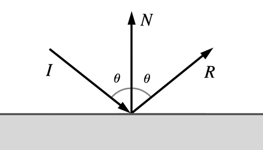
Reflection occurs when light bounces off of a reflective surface. In this post, we will only consider perfect mirror reflection, the case where all light bounces off at an angle equal to its incident angle. To simulate reflection in a virtual scene, we run this process backward, tracing a ray from the virtual camera through the scene, reflecting it off a surface, and determining where it intersects our cube map.
The Reflection Vertex Shader
To compute the cube map texture coordinates for a given vector, we need to find the vector that points from the virtual camera to the current vertex, as well as its normal. These vectors must both be relative to the world coordinate system. The uniforms we pass into the vertex shader include the model-to-world matrix as well as the normal matrix (which is the inverse transpose of the model-to-world matrix). This allows us to compute the necessary vectors for finding the reflected vector according to the formula given above.
Fortunately, Metal includes a built-in function that does the vector math for us. reflect takes two parameters: the incoming vector, and the surface normal vector. It returns the reflected vector. In order for the math to work correctly, both input vectors should be normalized in advance.
vertex ProjectedVertex vertex_reflect(device Vertex *vertices     [[buffer(0)]],
                                      constant Uniforms &uniforms [[buffer(1)]],
                                      uint vid                    [[vertex_id]])
{
    float4 modelPosition = vertices[vid].position;
    float4 modelNormal = vertices[vid].normal;

    float4 worldCameraPosition = uniforms.worldCameraPosition;
    float4 worldPosition = uniforms.modelMatrix * modelPosition;
    float4 worldNormal = normalize(uniforms.normalMatrix * modelNormal);
    float4 worldEyeDirection = normalize(worldPosition - worldCameraPosition);

    ProjectedVertex outVert;
    outVert.position = uniforms.modelViewProjectionMatrix * modelPosition;
    outVert.texCoords = reflect(worldEyeDirection, worldNormal);

    return outVert;
}
The output vertex texture coordinates are interpolated by the hardware and passed to the fragment shader we already saw. This creates the effect of per-pixel reflection, since every execution of the fragment shader uses a different set of texture coordinates to sample the cube map.
The Physics of Refraction
The second phenomenon we will model is refraction. Refraction occurs when light passes from one medium to another. One everyday example is how a straw appears to bend in a glass of water.
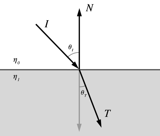
We won’t discuss the mathematics of refraction in detail here, but the essential characteristic of refraction is that the amount the light bends is proportional to the ratio between the indices of refraction of the two media it is passing between. The index of refraction of a substance is a unitless quantity that characterizes how much it slows down the propagation of light, relative to a vacuum. Air has an index very near 1, while the index of water is approximately 1.333 and the index of glass is approximately 1.5.
Refraction follows a law called Snell’s law, which states that the ratio of the sines of the incident and transmitted angles is equal to the inverse ratio of the indices of refraction of the media:
![]()
The Refraction Vertex Shader
The refraction vertex shader is identical to the reflection vertex shader, except that we call refract instead of reflect. refract takes a third parameter, which is the ratio between the two indices of refraction. kEtaRatio is a shader constant that represents the ratio between the indices of refraction of air and glass.
outVert.texCoords = refract(worldEyeDirection, worldNormal, kEtaRatio);
The refract function does the work of bending the vector about the normal to produce the transmitted vector, which once again is used as a set of texture coordinates to sample the cube map.
One obviously non-physical aspect of this simplified refraction model is that only the front-most surface of an object is visible. Additionally, the transport of light inside the object is ignored; instead it behaves like an infinitely-thin shell. Even with these shortcomings, the effect is impressive.
Using Core Motion to Orient the Scene
The app uses the orientation of the device to rotate the scene so that the torus always appears at the center, with the environment revolving around it. The Core Motion framework uses the various sensors in the iOS device (accelerometer, gyroscope, etc.) to determine where the device is pointed.
The Motion Manager
The CMMotionManager class is central to tracking device motion. After creating a motion manager instance, we should check if device motion is available. If it is, we may proceed to set an update interval and request that the motion manager start tracking motion. The following code performs these steps, requesting an update sixty times per second.
CMMotionManager *motionManager = [[CMMotionManager alloc] init];
if (motionManager.deviceMotionAvailable)
{
    motionManager.deviceMotionUpdateInterval = 1 / 60.0;
    CMAttitudeReferenceFrame frame = CMAttitudeReferenceFrameXTrueNorthZVertical;
    [motionManager startDeviceMotionUpdatesUsingReferenceFrame:frame];
}
Reference Frames and Device Orientation
A reference frame is a set of axes with respect to which device orientation is specified.
Several different reference frames are available. Each of them identifies Z as the vertical axis, while the alignment of the X axis can be chosen according to the application’s need. We choose to align the X axis with magnetic north so that the orientation of the virtual scene aligns intuitively with the outside world and remains consistent between app runs.
The device orientation can be thought of as a rotation relative to the reference frame. The rotated basis has its axes aligned with the axes of the device, with +X pointing to the right of the device, +Y pointing to the top of the device, and +Z pointing out of the screen.
Reading the Current Orientation
Each frame, we want to get the updated device orientation, so we can align our virtual scene with the real world. We do this by asking for an instance of CMDeviceMotion from the motion manager.
CMDeviceMotion *motion = motionManager.deviceMotion;
The device motion object provides the device orientation in several equivalent forms: Euler angles, a rotation matrix, and a quaternion. Since we already use matrices to represent rotations in our Metal code, they are they best fit for incorporating Core Motion’s data into our app.
Everyone has his or her own opinion about which view coordinate space is most intuitive, but I always choose a right-handed system with +Y pointing up, +X pointing right, and +Z pointing toward the viewer. This differs from Core Motion’s conventions, so in order to use device orientation data, we interpret Core Motion’s axes in the following way: Core Motion’s X axis becomes our world’s Z axis, Z becomes Y, and Y becomes X. We don’t have to mirror any axes, because Core Motion’s reference frames are all right-handed.
CMRotationMatrix m = motion.attitude.rotationMatrix;

vector_float4 X = { m.m12, m.m22, m.m32, 0 };
vector_float4 Y = { m.m13, m.m23, m.m33, 0 };
vector_float4 Z = { m.m11, m.m21, m.m31, 0 };
vector_float4 W = {     0,     0,     0, 1 };

matrix_float4x4 orientation = { X, Y, Z, W };
renderer.sceneOrientation = orientation;
The renderer incorporates the scene orientation matrix into the view matrices it constructs for the scene, thus keeping the scene in alignment with the physical world.
Conclusion
In the post we have investigated some of the possible uses of cube maps. Cube maps can be used for creating convincing backdrops to your virtual scene with skyboxes, and they also enable interesting effects such as reflection and refraction. Cube maps are a valuable addition to your Metal repertoire.
Download the sample code for this post here. To switch between reflection and refraction mapping, tap the screen. Have fun, and stay shiny!
Hi. Could you help me to create something like prism. In your sample you make refraction or reflection only from visible part of torus, but I need to create reflection on both parts of torus(not only torus any other figures). As example when you have two planes(second behind first), it’ll show refraction only for first plane.
Unfortunately, what you want to do is very difficult with forward rendering. As I mentioned in the article, this implementation of reflection/refraction is a hack that only accounts for the front-most surface of the figure. In order to see through the figure, accounting for both how light propagates in the refracting medium and other parts of the figure behind the front face, you would need to use a more sophisticated rendering algorithm, such as raytracing.
Thanks for your reply. I have idea to render two same figures with opposite normals directions. First will refract ray and get data from previously refracted second figure. But i don’t know how to implement this, and is it possible?
That sounds very similar to the approach in David Gosselin’s GDC 2004 talk, “Drawing a Diamond”.
Thanks! This was very useful. Could you please write a tutorial about deferred lightning? I’m currently stuck with that…
I absolutely intend to write about deferred shading. If not for the site, then in the book.
Great articles! Trying to catch up here.
Any suggestions how to modify the project/code for XCode 7 and Swift 2?
To the best of my knowledge all of the source on the site compiles on Xcode 7.x including the 7.2 beta. As for porting to Swift, it’s just a matter of rote translation. The bulk of the code is just imperative calls to Metal API, so it’s hard to imagine it getting more “Swifty” in translation.
I’m trying to get pan gesture controls in a similar implementation to this. I am having an issue where the camera keeps flipping upside down when you pan up and down on the screen. Not exactly sure what is going wrong with it.
validateFunctionArguments:3722: failed assertion `Vertex Function(vertex_reflect): the offset into the buffer uniforms that is bound at buffer index 1 must be a multiple of 256 but was set to 272.’
I suspect you’re getting this validation failure on a Mac rather than an iOS device? Some Mac GPUs have stricter buffer offset alignment requirements than others. The solution is to pad uniform data up to the next multiple of the alignment when copying uniforms. I’ll try to eventually get around to making this sample compatible with Macs.