In this article, we’ll take a look at a portion of the ModelIO framework we haven’t used so far: materials. In previous articles, we’ve used ModelIO to do the heavy lifting of loading 3D geometry, but have loaded and applied textures manually. This ad hoc approach works when we only have a base color map, but quickly grows tedious as materials become more complicated. Here, we’ll take a deep dive into ModelIO materials and learn how to use them to perform basic physically-based rendering (PBR).
You can find the sample code for this article here.
This is not a tutorial on physically-based rendering. PBR has been a hot topic for the past several years, and other people have written excellent tutorials on the subject. Joey de Vries’ series is probably the most approachable. Also consider taking a look at the documentation for Google’s brand-new mobile-first rendering engine Filament. For more theoretical background, consult the following papers and resources:
The focus here is on how ModelIO represents materials, deemphasizing how a shader might render them. For this reason, the shaders for this article are a pared-down version of Apple’s LOD with Function Specialization sample, which is worth studying.

A Quick Tour of ModelIO Materials
ModelIO is a remarkably flexible framework that allows us to easily load 3D models in a variety of formats, including Alembic (.abc), USD (.usd, .udsz), and OBJ. Each of these formats represents materials differently, so ModelIO provides an abstraction that generalizes over all of them.
The main class we’ll use from ModelIO is MDLMaterial. A ModelIO material contains a list of material properties (each an instance of MDLMaterialProperty). Each material property contains a value, which can be a float, a vector of floats, a color, a string or file URL, a texture, etc. Each property also has a semantic, which indicates how it should be used.
Take a look at the MDLMaterialSemantic enum to get acquainted with some of the properties a material can have. Here’s a subset:
enum MDLMaterialSemantic : UInt {
    case baseColor
    case metallic
    case roughness
    case sheen
    case sheenTint
    case clearcoat
    case clearcoatGloss
    case emission
    case userDefined
}
Many of these may be familiar from the so-called Disney BRDF, popularized by Brent Burley:
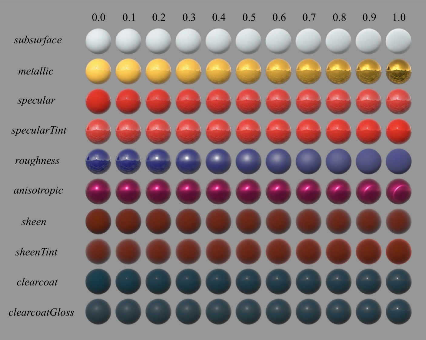
In ModelIO, many of these properties can take on different types of values. For example, if a material should have uniform roughness, its value could be a single float. On the other hand, if roughness varies over the surface, the value of the roughness material property could be a file URL that refers to a texture map containing a different roughness value for each pixel. These various property values are used by renderers such as SceneKit and the renderer in this article’s sample code to determine how each point on a surface should be shaded.
Revisiting ModelIO Import
We’ve used ModelIO previously, so this won’t be a comprehensive introduction. Instead, we’ll focus on a few narrow topics:
- Loading models with ModelIO
- Resolving texture properties into image data
- Generating additional vertex data with ModelIO
- Interoperating between ModelIO and MetalKit
Let’s look at each of these in turn.
Loading an Asset with ModelIO
There are numerous ways to create a ModelIO asset (MDLAsset), but since the sample uses a model that is embedded in the app bundle, we’ll first ask the bundle for the URL of the model:
let modelURL = Bundle.main.url(forResource: "scene", withExtension: "obj")
Then, we can load the asset. Note that we provide a buffer allocator (to ensure the mesh data is Metal-compatible), but we don’t provide a vertex descriptor. The reason for this will be explained below.
let asset = MDLAsset(url: url, vertexDescriptor: nil, bufferAllocator: bufferAllocator)
Resolving Texture Properties into Image Data
As mentioned previously, material properties can contain a texture that supplies a property value on a per-pixel basis. The sample code uses this extensively: the model in the sample has separate textures for base color, roughness, metalness, and normals. Each of these properties is initially stored as a string or a URL. In order to convert these properties into image data we can actually use in Metal, we need to ask the asset to resolve these references and load the corresponding image data:
asset.loadTextures()
The loadTextures() method iterates all of the materials in the asset and—if they are strings or URLs—loads their associated image data. The material property will then report its type as .texture and will have an MDLTextureSampler object as its textureSamplerValue property.
The MDLTextureSampler type does not contain a texture that can be used by Metal directly; rather, it contains image data in a format that can be easily loaded into a MTLTexture for drawing. It also contains other properties indicating the preferred transform and filtering modes for the texture. These could, respectively, be turned into a texture matrix and a sampler state to affect how Metal samples the textures, but for our simple use case, we’ll ignore these properties.
A Basic Material Class
To hold the MTLTextures with which we want to draw meshes, we’ll create our own Material class, which is nothing more than a container for the textures corresponding to the material properties our shader knows how to handle:
class Material {
    var baseColor: MTLTexture?
    var metallic: MTLTexture?
    var roughness: MTLTexture?
    var normal: MTLTexture?
    var emissive: MTLTexture?
    // ...
}
To initialize one of these objects, we provide a MDLMaterial instance and ask for each of the relevant material properties in turn, converting their images into textures we can actually use:
init(material sourceMaterial: MDLMaterial?, textureLoader: MTKTextureLoader) {
    baseColor = texture(for: .baseColor, in: sourceMaterial, textureLoader: textureLoader)
    metallic = texture(for: .metallic, in: sourceMaterial, textureLoader: textureLoader)
    roughness = texture(for: .roughness, in: sourceMaterial, textureLoader: textureLoader)
    normal = texture(for: .tangentSpaceNormal, in: sourceMaterial, textureLoader: textureLoader)
    emissive = texture(for: .emission, in: sourceMaterial, textureLoader: textureLoader)
}
The texture(for:in:textureLoader:) method is the heart of this class. It uses MTKTextureLoader‘s convenience method newTexture(texture:options:) to convert an MDLTexture into an MTLTexture:
func texture(for semantic: MDLMaterialSemantic, in material: MDLMaterial?, textureLoader: MTKTextureLoader) -> MTLTexture? {
    guard let materialProperty = material?.property(with: semantic) else { return nil }
    guard let sourceTexture = materialProperty.textureSamplerValue?.texture else { return nil }
    let wantMips = materialProperty.semantic != .tangentSpaceNormal
    let options: [MTKTextureLoader.Option : Any] = [ .generateMipmaps : wantMips ]
    return try? textureLoader.newTexture(texture: sourceTexture, options: options)
}
Note that we casually ignore properties that are not texture-based here. To keep things simple, the shader relies on a texture being present for each of these properties, so when there isn’t one available, we’ll substitute an appropriate default texture.
We’ll create an instance of this Material class for each MDLMaterial instance we encounter when converting the ModelIO meshes into their MetalKit counterparts. First, though, we need to ask ModelIO to generate a little data for us.
Generating Tangent Frames
In order to do normal mapping, which allows us to greatly increase the apparent complexity of surfaces without using additional geometry, we need a set of orthonormal axes called a tangent frame for each vertex.
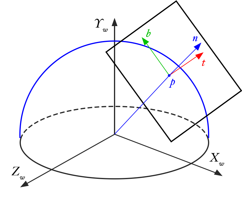
This tangent frame can be constructed based on the vertex normals 1 of a model, but many model files don’t include this information. Fortunately, ModelIO gives us a facility for adding this data to our meshes at runtime.
In order to augment our meshes with tangent data, we need to iterate over the meshes and call the addOrthTanBasis(forTextureCoordinateAttributeNamed: normalAttributeNamed:tangentAttributeNamed:) method. ModelIO assets can contain various types of objects: cameras, lights, meshes, etc. In this case, we’re only concerned with meshes, so we can use a method called childObjects(of:) to retrieve the MDLMeshes in the asset:
for sourceMesh in asset.childObjects(of: MDLMesh.self) as! [MDLMesh] {
    sourceMesh.addOrthTanBasis(forTextureCoordinateAttributeNamed: MDLVertexAttributeTextureCoordinate,
                               normalAttributeNamed: MDLVertexAttributeNormal,
                               tangentAttributeNamed: MDLVertexAttributeTangent)
    sourceMesh.vertexDescriptor = vertexDescriptor
}
Once the mesh has tangent data, we set its vertexDescriptor to a vertex descriptor we previously constructed. This is a deceptively simple operation that can wind up being quite expensive, as it asks ModelIO to lay out the vertex data (positions, normals, tangents, and texture coordinates) in the way we specify. That’s why we didn’t supply a vertex descriptor when creating the asset: there’s no reason to pay this cost twice if we know we’re going to mutate the mesh data in this way.
For reference, here’s the vertex descriptor we use. It’s similar to those we’ve used in the past, with the addition of an attribute to hold the tangent:
let vertexDescriptor = MDLVertexDescriptor()
vertexDescriptor.attributes[0] = MDLVertexAttribute(name: MDLVertexAttributePosition,
                                                    format: .float3,
                                                    offset: 0,
                                                    bufferIndex: VertexBufferIndex.attributes.rawValue)
vertexDescriptor.attributes[1] = MDLVertexAttribute(name: MDLVertexAttributeNormal,
                                                    format: .float3,
                                                    offset: MemoryLayout<Float>.size * 3,
                                                    bufferIndex: VertexBufferIndex.attributes.rawValue)
vertexDescriptor.attributes[2] = MDLVertexAttribute(name: MDLVertexAttributeTangent,
                                                    format: .float3,
                                                    offset: MemoryLayout<Float>.size * 6,
                                                    bufferIndex: VertexBufferIndex.attributes.rawValue)
vertexDescriptor.attributes[3] = MDLVertexAttribute(name: MDLVertexAttributeTextureCoordinate,
                                                    format: .float2,
                                                    offset: MemoryLayout<Float>.size * 9,
                                                    bufferIndex: VertexBufferIndex.attributes.rawValue)
vertexDescriptor.layouts[VertexBufferIndex.attributes.rawValue] = MDLVertexBufferLayout(stride: MemoryLayout<Float>.size * 11)
A Simple Node Class
Taking a step back from the scene graph implementation we created previously, we need a small class to collect the mesh data, material, and model-to-world transform for each object in the world. Here’s a simplified Node type that will do the trick:
class Node {
    var modelMatrix: float4x4
    let mesh: MTKMesh
    let materials: [Material]

    init(mesh: MTKMesh, materials: [MDLMaterial?]) {
        modelMatrix = matrix_identity_float4x4
        self.mesh = mesh
        self.materials = materials
    }
}
The materials array holds an instance of our Material class for each submesh its mesh contains. Since we can’t store our converted material instances directly on the submeshes, this is the next best thing.
Mapping from ModelIO to MetalKit
To go from ModelIO meshes to MetalKit meshes, which are what we’ll actually be drawing, we can use a class method on MTKMesh called newMeshes(asset:device:). This method returns a tuple comprised of the original MDLMeshes in the asset as well as their corresponding MTKMesh instances:
guard let (sourceMeshes, meshes) = try? MTKMesh.newMeshes(asset: asset, device: device) else {
    fatalError("Could not convert ModelIO meshes to MetalKit meshes")
}
We want to create a node for each mesh in the asset and a material for each submesh. To do this, we zip together the source mesh and mesh collections so we can iterate them in parallel:
for (sourceMesh, mesh) in zip(sourceMeshes, meshes) {
    var materials = [Material]()
    for sourceSubmesh in sourceMesh.submeshes as! [MDLSubmesh] {
        let material = Material(material: sourceSubmesh.material, textureLoader: textureLoader)
        materials.append(material)
    }
    let node = Node(mesh: mesh, materials: materials)
    nodes.append(node)
}
Drawing with Physically-Based Materials
In order to draw, we’ll follow the pattern established in Modern Metal, Part 2: create a command encoder, configure its render pipeline state and other state that will remain constant during the frame, then call a draw method that handles the business of drawing a single mesh. As mentioned previously, we don’t have a scene graph this time around—just a list of nodes—so the way in which we compute transforms is a bit simplified.
Drawing
In order to draw a node, we iterate the vertex buffer it contains and set them on the command encoder at the appropriate index and offset. The shader is configured to understand which buffer it should read vertex data from.
let mesh = node.mesh

for (bufferIndex, vertexBuffer) in mesh.vertexBuffers.enumerated() {
    commandEncoder.setVertexBuffer(vertexBuffer.buffer, offset: vertexBuffer.offset, index: bufferIndex)
}
We then iterate the submeshes and issue a drawIndexedPrimitives call for each one:
for (submeshIndex, submesh) in mesh.submeshes.enumerated() {
    let material = node.materials[submeshIndex]
    bindTextures(material, commandEncoder)
    let indexBuffer = submesh.indexBuffer
    commandEncoder.drawIndexedPrimitives(type: submesh.primitiveType,
                                         indexCount: submesh.indexCount,
                                         indexType: submesh.indexType,
                                         indexBuffer: indexBuffer.buffer,
                                         indexBufferOffset: indexBuffer.offset)
}
Before each draw call, we pass the submesh’s material to a method called bindTextures, which sets the material’s textures on the command encoder. When a property does not have a texture, it substitutes a default texture (which is black in most cases, with the exception of the normal map):
func bindTextures(_ material: Material, _ commandEncoder: MTLRenderCommandEncoder) {
    commandEncoder.setFragmentTexture(material.baseColor ?? defaultTexture, index: TextureIndex.baseColor.rawValue)
    commandEncoder.setFragmentTexture(material.metallic ?? defaultTexture, index: TextureIndex.metallic.rawValue)
    commandEncoder.setFragmentTexture(material.roughness ?? defaultTexture, index: TextureIndex.roughness.rawValue)
    commandEncoder.setFragmentTexture(material.normal ?? defaultNormalMap, index: TextureIndex.normal.rawValue)
    commandEncoder.setFragmentTexture(material.emissive ?? defaultTexture, index: TextureIndex.emissive.rawValue)
}
Basics of Image-Based Lighting
Having physically-based materials is great, but they won’t look very good if we don’t have equally plausible lights in our scene. Unfortunately, realistic lighting is notoriously difficult to achieve. Fortunately, a lot of clever techniques have been devised to make real-time lighting tractable.
One of these techniques is image-based lighting. In contrast to the analytic lights we’ve used previously, which have a single position or direction, image-based lights represent an entire lighting environment, the radiance of the scene in all directions. We’ll use a cubemap to capture this lighting and simply sample from the map to get the quantity of incoming light, rather than having to take numerous samples and numerically compute complex integrals at runtime.
For more information on image-based lighting as it’s commonly performed, consult this tutorial on LearnOpenGL.com. The sample code includes a texture that has been pre-filtered using the method described there.
We send the lighting cubemap into our shader by setting on our command encoder, as we did with the other textures:
commandEncoder.setFragmentTexture(irradianceCubeMap, index: TextureIndex.irradiance.rawValue)
A Whirlwind Tour of a PBR Shader
It’s important to preface this section by saying that the shader in the sample code is not optimized, nor is it of the highest quality. In other words, don’t use it as a reference implementation.
The vertex shader looks pretty similar to vertex shaders we’ve used in the past, with the exception that instead of just transforming the normal by the normal matrix, we also transform the tangent vector, then take the cross product of the two, producing the bitangent vector that completes our tangent frame.
vertex VertexOut vertex_main(Vertex in [[stage_in]],
                             constant Uniforms &uniforms [[buffer(vertexBufferIndexUniforms)]])
{
    VertexOut out;
    out.position = uniforms.modelViewProjectionMatrix * float4(in.position, 1.0);
    out.texCoords = in.texCoords;
    out.normal = uniforms.normalMatrix * in.normal;
    out.tangent = uniforms.normalMatrix * in.tangent;
    out.bitangent = uniforms.normalMatrix * cross(in.normal, in.tangent);
    out.worldPos = (uniforms.modelMatrix * float4(in.position, 1.0)).xyz;
    return out;
}
The fragment shader is somewhat more involved, so I’ll only show its skeleton here. Essentially, all of the parameters needed by the lighting calculations are bundled up into a LightingParameters struct, which is then passed to subroutines for computing the diffuse and specular terms of the final color, which is returned as the color of the fragment.
fragment half4 fragment_main(VertexOut in                     [[stage_in]],
                             constant Uniforms &uniforms      [[buffer(fragmentBufferIndexUniforms)]],
                             texture2d<float> baseColorMap    [[texture(textureIndexBaseColor)]],
                             texture2d<float> metallicMap     [[texture(textureIndexMetallic)]],
                             texture2d<float> roughnessMap    [[texture(textureIndexRoughness)]],
                             texture2d<float> normalMap       [[texture(textureIndexNormal)]],
                             texture2d<float> emissiveMap     [[texture(textureIndexEmissive)]],
                             texturecube<float> irradianceMap [[texture(textureIndexIrradiance)]])
{
    LightingParameters parameters;
    // ...
    float3 color = diffuseTerm(parameters) + specularTerm(parameters);
    return half4(half3(color), baseColor.a);
}
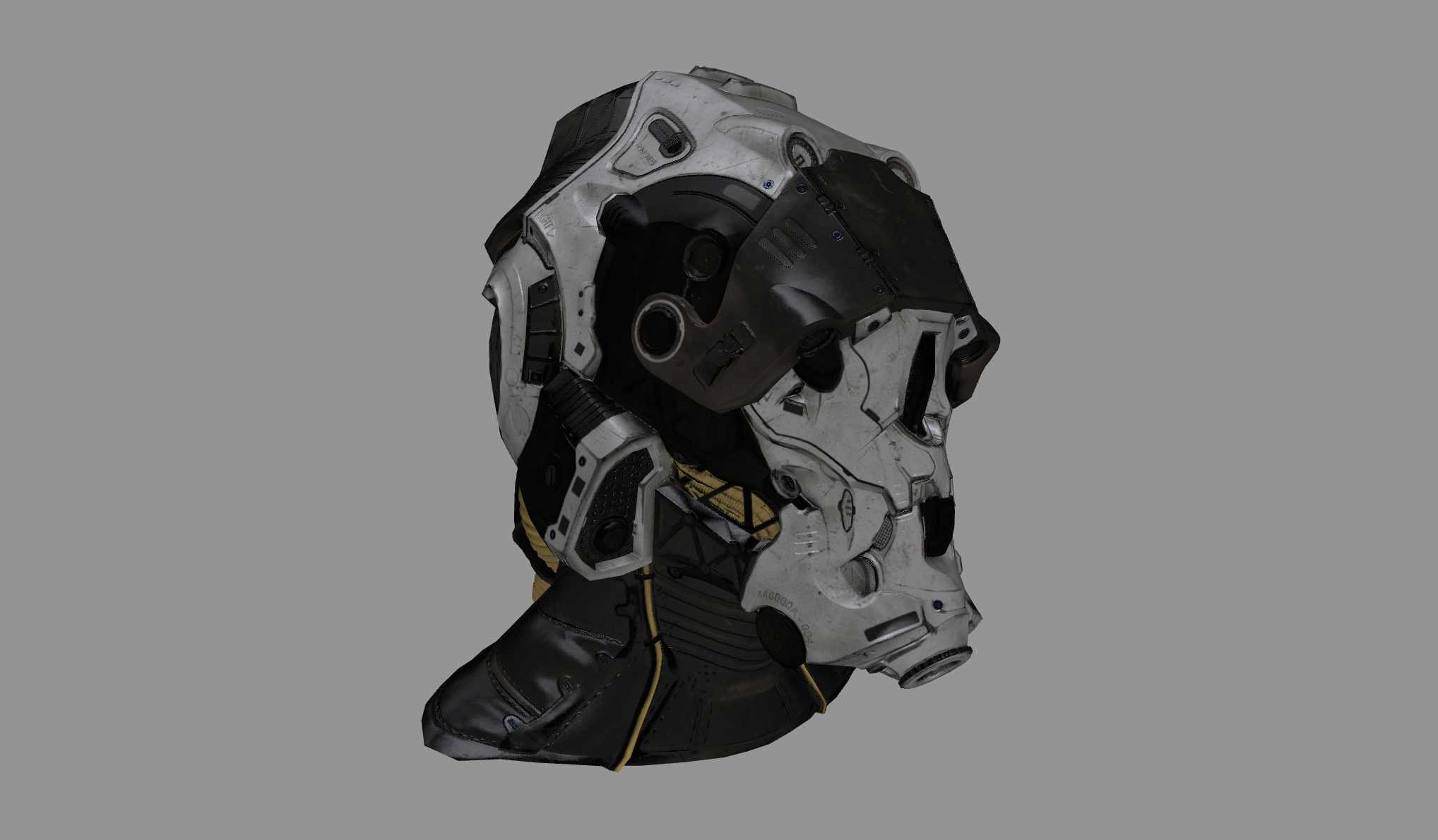
If you run the sample project on your Mac or iOS device, you can see the result of our work, which looks as follows:
Conclusion
In this article, we looked at the ModelIO material model, a system that allows us to represent rich materials that can be used for physically-based rendering. We saw how to load an asset, how to convert image data in ModelIO materials into Metal textures, and how to convert ModelIO meshes into MetalKit meshes that we could render with Metal.
Thanks to Noah Witherspoon and Clémentine Dugrand for proofreading.
Hi Warren,
Great article, and the render looks super!
Regarding the construction of the tangent basis, since the function addOrthTanBasis uses texture coordinates and normals in it’s calculation of the tangent, it appears it does follow the matrix inverse method described in Schüler’s article (or more concisely explained here:
https://gamedev.stackexchange.com/questions/68612/how-to-compute-tangent-and-bitangent-vectors ). So I think it is actually safe to use this function provided that the correct normals are already present on the model.
Where you write ‘This tangent frame can be constructed based on the vertex normals of a model, but many model files don’t include this information. Fortunately, ModelIO gives us a facility for adding this data to our meshes at runtime.’ you could maybe clarify that this is done with addNormals, not addOrthTanBasis, since addOrthTanBasis only calculates the correct tangent, based on the normals and texture coordinate attributes already present in the model, and if the normals aren’t present, they must first be calculated using addNormals (which takes the normalised cross product of 2 edges) before the function addOrthTanBasis can be called.
Kind regards,
Tony