The purpose of this article is to describe and explore a foundational concept in Metal: vertex descriptors. Vertex descriptors are the glue between your application code (written in Objective-C or Swift) and your shader functions (written in the Metal Shading Language). They describe the shape of data consumed by your shaders.
When I was writing the first articles for this site (over four years ago), I didn’t have a firm grasp on the purpose of vertex descriptors, and since their use is optional, this omission persisted for far too long. The sample code for most articles has been updated periodically, and most samples now use vertex descriptors, so it seemed fitting to write about them.
You can download the sample project for this article here.
In order to discuss vertex descriptors, we need to go back to the fundamentals of data and functions.
Functions and Data
Generally speaking, the purpose of a function is to transform data. Shader functions are no different. For example, a vertex function transforms vertices from whatever space they originate in (often model space) into clip space. A fragment function transforms rasterized data into the final color of a fragment.
Since most functions operate on data supplied externally (as opposed to data generated procedurally), we need a way to get data into our functions. For this reason, they take parameters. Metal shader functions likewise take parameters, but since these functions are “called” by the GPU while executing drawing commands, we don’t pass arguments directly to them. This difference is a source of confusion for many newcomers to Metal.
So how does data get into shader functions? To answer that, we need to first ask what do the data that we want to use in our shader functions look like?
The Shape of Data
Suppose we have a structure in our Metal shader file that represents the data associated with a single vertex:
struct Vertex {
    float3 position;
    float3 color;
};
In this struct, we’re packaging a (model-space) position and color together. This is simply an example; as in regular application code, a function is written to take whatever data it needs to do its job.
In our application code, we might have an array of these structures, one for each vertex. Before we draw this data, we need to copy it into a Metal buffer, which is a block of memory that can be read by the GPU. This is the first step toward being able to use the data from inside a Metal shader function.
Getting Data into Buffers
In Objective-C, we’d probably use memcpy to perform this copy:
memcpy(buffer.contents, vertices, sizeof(Vertex) * vertexCount);
In Swift, we have the option of being slightly safer by first binding the buffer’s contents to our structure’s type before copying into it:
let bufferPoints = buffer.contents().bindMemory(to: Vertex.self,
                                                capacity: vertices.count)
bufferPoints.assign(from: &vertices, count: vertices.count)
Note that this is still risky, since as of this writing Swift does not provide guarantees about how struct members are laid out in memory. Struct members can be arbitrarily reordered or padded by Swift, breaking the expectation that the Swift struct has the same layout as its corresponding Metal struct. This can be mitigated by declaring structs in C or Objective-C instead and importing them into Swift via a bridging header, which affords stronger guarantees about member layout.
If our application code is one side of the application-shader bridge, the shader function is the other side. Before we talk about the bridge between them, let’s talk about how data is consumed in a shader function.
Using Data in Functions
When we aren’t using a vertex descriptor, we’re obligated to look up vertex data in our buffers manually. We do this by writing our vertex function to take pointers to one or more buffers, as well as a special parameter attributed with the vertex_id attribute. This parameter is populated with the current vertex index whenever the function is invoked on the GPU. Here’s the signature of a simple vertex function:
vertex VertexOut vertex_main(
    device Vertex *vertices [[buffer(0)]],
    uint vid                [[vertex_id]])
In the body of the function, we then manually fetch the current vertex data from the provided index:
Vertex vertex = vertices[vid];
Determining the vertex data to pass on to the fragment shader is a matter of accessing each piece of vertex data, transforming it, and returning a structure from the function. For example, we might multiply the position by a transformation matrix to move it into clip space, and also pass through the vertex color directly:
VertexOut out;
out.position = uniforms.modelViewProjectionMatrix * float4(vertex.position, 1);
out.color = vertex.color;
return out;
So now we know how to retrieve and operate on vertex data in a vertex function, but how do we get data from our buffers into functions in the first place? To cross that bridge, we need to talk about an abstraction that’s unique to Metal: argument tables.
Argument Tables
You can think of an argument table as a list of resources. A command encoder has an argument table for each type of resource that you can supply to a shader function: buffers, textures, and samplers.
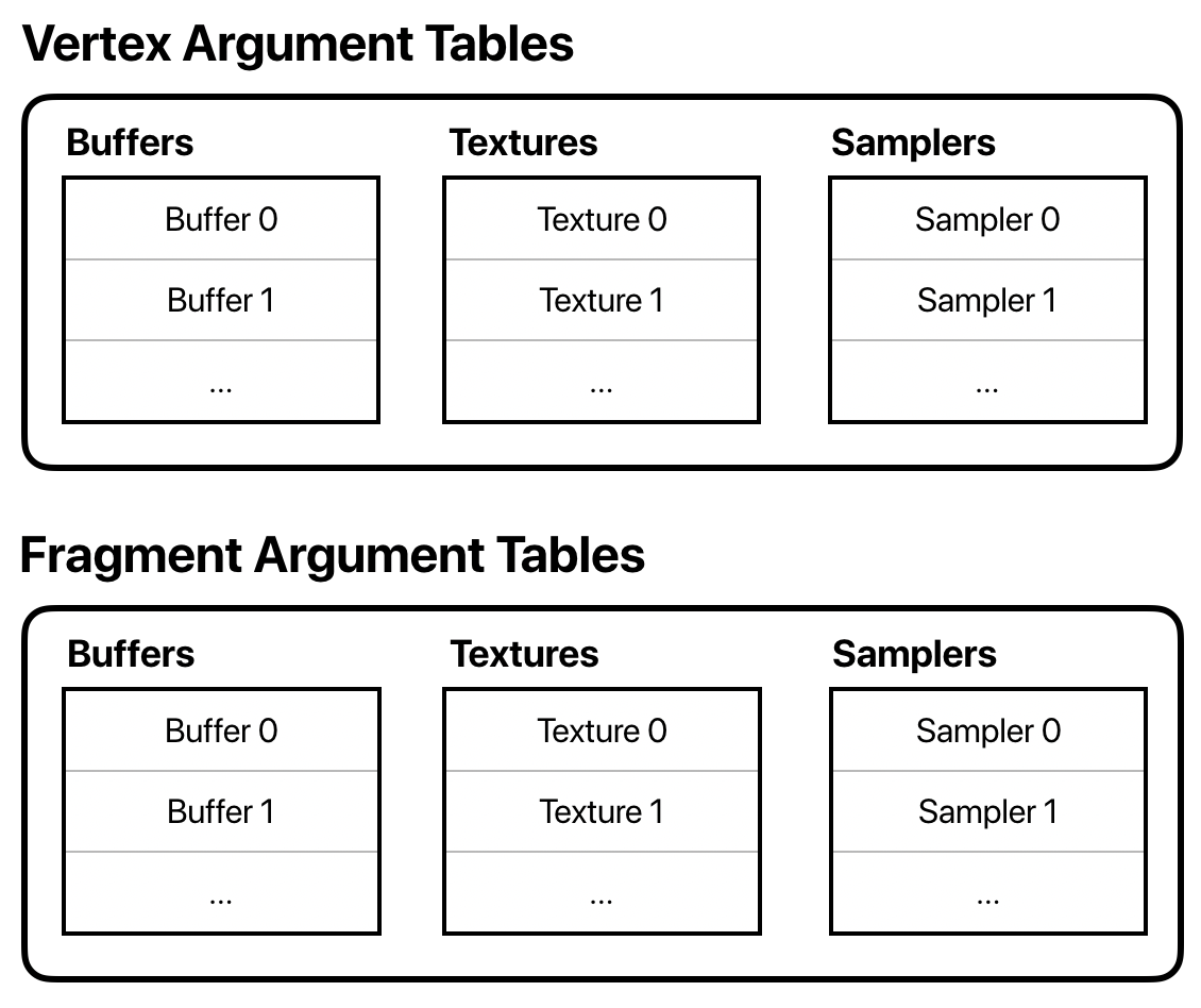
The number of entries (slots) in each list depends on the device, but you can generally assume you have at least 31 buffer and texture entries, and 16 sampler entries.
Setting Argument Table Entries
Rather than an actual data structure, an argument table is more a way of conceptualizing the collection of resources that are used by a particular draw call.
Each type of command encoder has methods for setting entries in its argument tables. In the case of the render command encoder, we have separate sets of argument tables for the vertex and fragment function, since they often operate on different data.
For example, if we want to set a buffer as the first entry in the vertex function’s argument table (index 0), we would do the following:
renderCommandEncoder.setVertexBuffer(vertexBuffer, offset: 0, index: 0)
In addition to telling the command encoder which argument buffer slot to set, you can provide an offset, which is the number of bytes from the beginning of the buffer where data should start to be read from.
Interleaved and Non-interleaved Data
Due to the popularity of the object-oriented paradigm, it is common and natural to want to think of a vertex as one thing, an object that contains all the data relevant to it. But, the GPU doesn’t have any concept of what a vertex is. All it cares about is that a clip-space position is somehow returned from the vertex function.
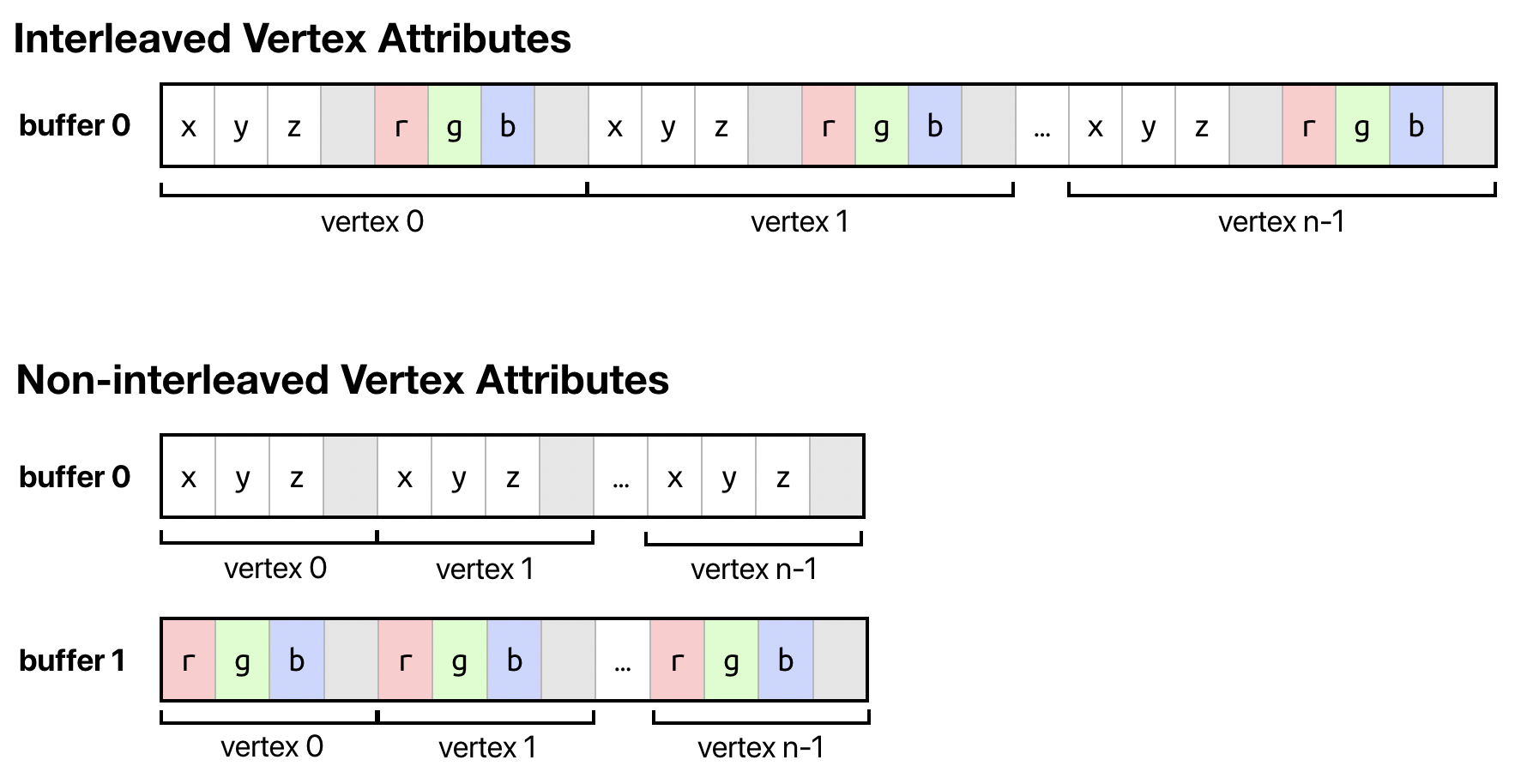
From a different perspective, then, we might imagine the attributes of our vertices as coming from separate streams, and keep the data for each attribute contiguous in memory: one area for positions, one for normals, one for colors, and so on.
This perspective has some notable benefits. For one, it means that we can access vertex data from different vertex functions without wasting bandwidth or cache space. If a vertex is processed by a pipeline that generates a shadow map, that vertex function may only need the vertex’s position, and not any other data. If we store all of the data for a vertex contiguously, the GPU has to stride farther in memory to get to the next bit of data it needs to operate on. Furthermore, it may be difficult to pack data together in a struct in a way that optimizes storage or read performance, owing to both cache effects and alignment requirements.
When the attributes for a single vertex are stored contiguously, we say that the data is interleaved, while if the data for a particular attribute of all vertices are stored contiguously (whether in one buffer or several), the data is non-interleaved.
Reading Vertex Data with Automatic Fetch
Fortunately, Metal gives us a lot of flexibility when it comes to how we arrange our data in memory. It achieves this by abstracting how vertices are represented in shaders versus how they are laid out in buffers. To do this, we apply attributes to the members of our vertex struct, providing a unique attribute index for each:
struct Vertex {
    float3 position [[attribute(0)]];
    float3 color    [[attribute(1)]];
};
These attribute attributes (confusing, I know) allow us to refer to each piece of data by index, rather than caring about exactly where it resides in memory.
Rather than taking a pointer to a particular buffer in the argument table, our vertex function can now take a parameter attributed with the stage_in attribute:
vertex VertexOut vertex_main(Vertex vertex [[stage_in]])
What effect does this attribute have, and how does the incoming vertex struct get filled in? The answer is that your vertex function is patched by the shader compiler with instructions that tell the GPU where each attribute should be fetched from. This feature is called vertex fetch, and is enabled through the use of vertex descriptors, which are the topic of the next section.
Vertex Descriptors
A vertex descriptor (MTLVertexDescriptor) is the mapping between buffers and vertex function parameters. A vertex descriptor consists of a number of attributes and one or more layouts. In essence, an attribute describes the size and location of a single vertex property (position, texture coordinates, etc.), while a layout describes a single buffer. Most particularly, a layout has a stride that indicates the distance in bytes between vertices.
Interleaved and Non-interleaved Vertex Descriptors
The way in which vertex data is read by the GPU is entirely based on the vertex descriptor associated with the render pipeline state.
For example, consider the case where we want to keep all of our vertex data interleaved in a single buffer. Then, for the sample vertex struct above, we might construct our vertex descriptor as follows:
let vertexDescriptor = MTLVertexDescriptor()
vertexDescriptor.attributes[0].format = .float3
vertexDescriptor.attributes[0].bufferIndex = 0
vertexDescriptor.attributes[0].offset = 0
vertexDescriptor.attributes[1].format = .float3
vertexDescriptor.attributes[1].bufferIndex = 0
vertexDescriptor.attributes[1].offset = MemoryLayout<float3>.stride
vertexDescriptor.layouts[0].stride = MemoryLayout<float3>.stride * 2
We have two attributes, and their indices match the indices we specified in the vertex struct. We indicate that the second attribute is at an offset of the size of the first member from the beginning of the struct, since they are laid out next to one another in memory.
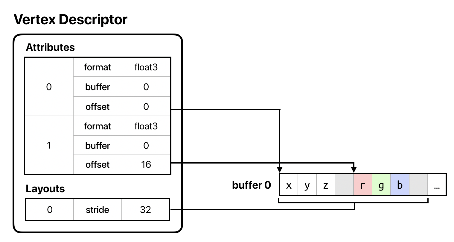
The buffer index in each attributes indicates to which argument table slot its corresponding buffer will be assigned; in this case, both attributes are in buffer 0. Since both attributes are in the same buffer, we have just one layout, and we set its stride to the sum of the size of the vertex struct members to indicate that our vertices are tightly packed together in the buffer.
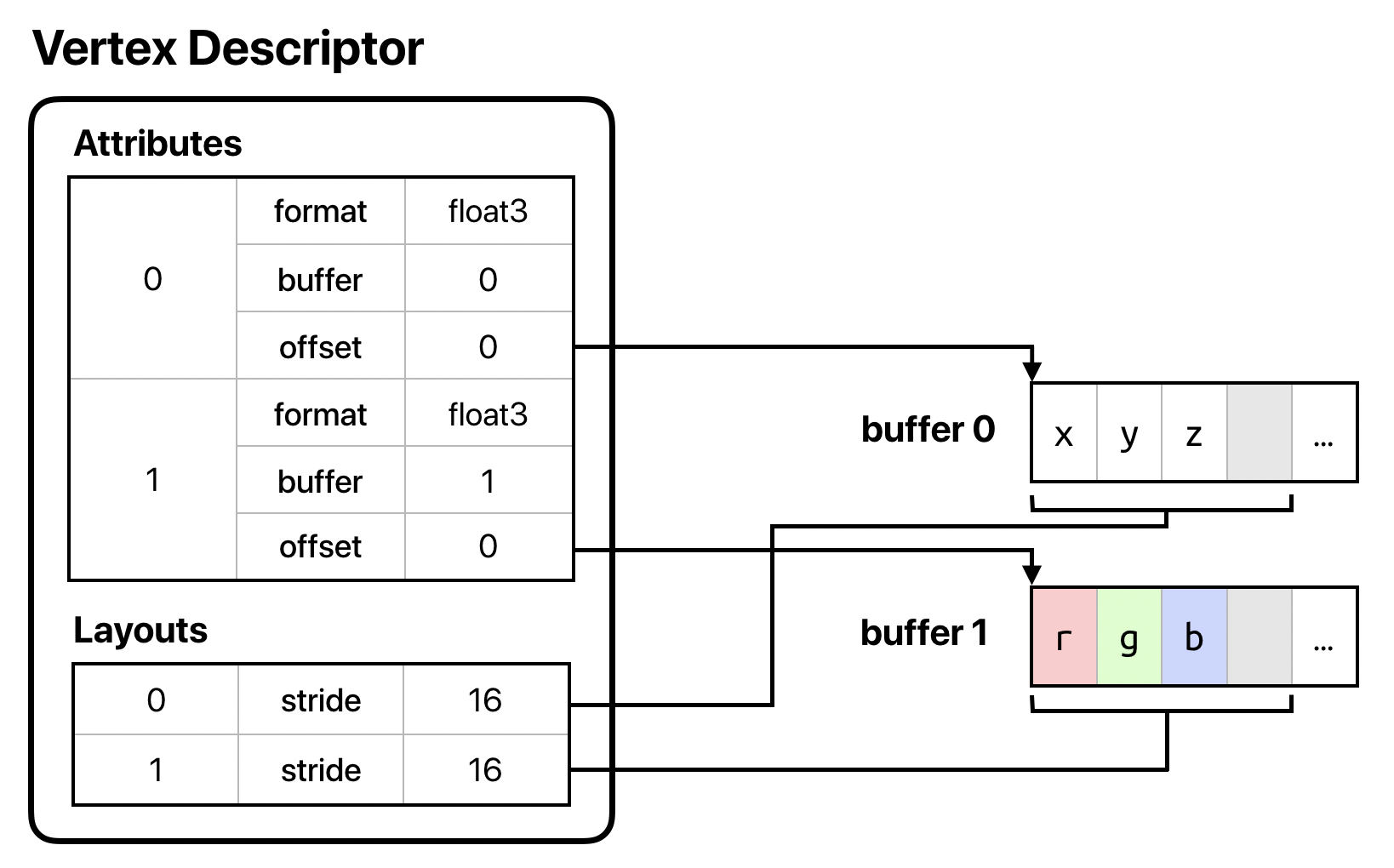
What if we wanted to de-interleave our data and provide it in two separate buffers? In this case, we’d still have two attributes at the same indices, but we’d change the offset of the second attribute to 0 to indicate that the first vertex’s data starts at the beginning of the buffer. Then, we’d add a second layout and set the stride of both layouts to be the width of a single struct member, since the data for each attribute has now been made independent:
let vertexDescriptor = MTLVertexDescriptor()
vertexDescriptor.attributes[0].format = .float3
vertexDescriptor.attributes[0].bufferIndex = 0
vertexDescriptor.attributes[0].offset = 0
vertexDescriptor.attributes[1].format = .float3
vertexDescriptor.attributes[1].bufferIndex = 1
vertexDescriptor.attributes[1].offset = 0
vertexDescriptor.layouts[0].stride = MemoryLayout<float3>.stride
vertexDescriptor.layouts[1].stride = MemoryLayout<float3>.stride
Step Functions and Step Rates
Attributes and layouts are only part of the vertex descriptor story. So far, we’ve been considering the case where we want to fetch new data each time our vertex function is called. Under some circumstances, we want to fetch data less often. For example, if we’re doing instanced rendering, we might want a particular attribute to remain the same across all vertices for an instance. Similarly, if we’re tessellating, some attributes will vary on a per-control-point or per-patch basis.
Vertex descriptors allow for this. Vertex descriptor layouts have two properties in addition to their stride that indicate the frequency with which data should be fetched: the step function and step rate.
Consult the documentation for step functions and step rate for more details on how to use these properties. They are somewhat specialized, but I didn’t want to neglect mentioning them, lest you get the impression that vertex descriptors are less powerful than they are.
Conclusion
In this article, we’ve covered a topic that has been long-neglected on this blog, vertex descriptors. You’ve seen how vertex descriptors can be used to decouple the layout of data in your application from how that data is loaded in your shader functions. You’ve also seen that, due to this decoupling, you can separate vertex data into multiple buffers in order to make it more efficient to use the same data with different render pipelines. Your Metal apps should use vertex descriptors whenever possible, since vertex descriptors are the rare kind of abstraction that aids both performance and code maintenance.
You can download the sample project for this article here.
Best Practices for Vertex Data
- Use vertex descriptors to stay flexible in how you lay out data in memory without taking a run-time performance hit.
- Prefer to use non-interleaved data, especially when not every vertex attribute is used in every shader, or when your vertices otherwise wouldn’t be tightly packed in the buffer.
- Remember that using non-interleaved data doesn’t necessarily mean using separate buffer objects; you can bind the same buffer to multiple argument slots with different offsets.
Fantastic article, thanks
Great article! Thank you.
Warren, I’m very new to Metal Frame work. but this is bugging me from day one in this platform. What’s going on with this whole SIMD business in Apple Frameworks?
1- SIMD in swift 5 library ( which is more about the vectors and no matrix as far as I understand )
2- simd in simd.h ( which is basically all the simd_floatNxM types and it is available to C,Swift and Metal)
3- simd in Accelerate Module
My Questions are;
1- why is there three places in Xcode documenting that you can find simd?
( one in the main listing part and one in subsection of Accelerate framework and obviously one in Swift framework)
2- When you try to import simd module in a swift code, Xcode (I’m in Xcode 11 with swift 5) In code complition, Xcode will cross it. Looks like that this module is deprecate. it doesn’t say like that, but seems like it. Why is that?
3- Again, Based on my versions of Xcode and swift, I can freely use any simd function and data type in Accelerate framework with absolutely no need to even import the accelerate module. so why they never mentioned that this simd.h is already in Swift API ? ( I’m not talking about SIMD4 . I’m talking about simd_float4x4 for example ) what is the underlying relation between these two ?
4- In a sample code from apple ( In WWDC 2016 , Adopting Metal Part 2, just after your session ) In a bridge header file, all the data structs are padded until they reach to 264 byte size and stride in a very particular way by floats and matrices. I get the whole 64 bit story, but why they did that kind of padding?
And
Thank you for this awesome website.
Thank you….
1) I think the redundancy in the Accelerate docs is just a convenience; as far as I know, Accelerate doesn’t define (or even directly import) any SIMD types. As for Swift, SIMD types were recently added to the standard library, and thus there are different typenames exposed by Swift (as opposed to C, C++, and Objective-C). The underlying functionality (as well as the size and alignment of the various types) agree among both implementations.
2) I suspect this is a bug, but it’s also not necessary to import the simd module in Swift, since all existing SIMD functionality is now exposed in the Swift standard library.
3) I think
simd_float4x4is now exposed as the preferred 4×4 matrix type via the Swift standard library, since they haven’t yet provided matrix and quaternion types that match theSIMD4, etc., generic types. That’s why it’s available without imports.4) They’re padded up to 256 bytes, since some GPUs require offsets into vertex buffers to be multiples of 256. See the note about constant address space buffers in the API docs.
Warren
I have a problem with the non interval fashion. I tried multiple times, I think it is not possible to set them to start from buffer index other than zero.
Is it true?
I checked every detail and the results was the same.
Try to send them from buffer 2 and 3 ….
I never tested this with interval system but I think it is relate to [[stage_in]] . It can’t start from anything else
Maybe Im mistaking. I don’t know.
I want to set my frame constants to buffer 0.
Per object transforms to buffer 1.
And mesh vertex buffers to 2 and 3 and the rest of the buffers.
Obviously this is a very different era but to the limited extent that it may be relevant: Apple’s advice back in the PowerVR and OpenGL ES days was always, always to use interleaved arrays. But with fixed-pipeline ES 1 only recently in the rearview mirror I guess most engines still had pretty simple vertex descriptions and you could assume that most vertex shaders would use most vertex fields.
Regardless, I’m only just now trying to get on top of Metal so this site is amazing. I’m extremely grateful.
Hi Warren,
How does metal know the order of attributes? Both seems to be working.
position, normal, color
or
position, color, normal
vertexDescriptor.attributes[0].format = .float3
vertexDescriptor.attributes[0].bufferIndex = 0
vertexDescriptor.attributes[0].offset = 0
vertexDescriptor.attributes[1].format = .float3
vertexDescriptor.attributes[1].bufferIndex = 0
vertexDescriptor.attributes[1].offset = 12
vertexDescriptor.attributes[2].format = .float3
vertexDescriptor.attributes[2].bufferIndex = 0
vertexDescriptor.attributes[2].offset = 36
Thanks a lot.
One of the benefits of using a vertex descriptor is that you no longer have to be as rigid with the layout or type of the vertex attributes in your shader code. As long as the indices of the attributes in your shaders match the indices of the attributes in your vertex descriptor, the vertex data will be fetched correctly (assuming that the rest of the vertex descriptor accurately describes the data in the buffer(s)).
Thank you for all these very clear articles and exemplary samples, Warren; I think they’re the best on the web.
Is there a possibility that you could write a blog some time about ViewPorts? I’ve read Apple’s documentation around pp85-88 of the MSL manual and I find it impossible to implement. How, for example, does one append viewport identifiers to generate four separate outputs in, say, a 2×2 view?
Is the flexibility of the sequence of declarations you mention in your reply to AZ on 4th October 2020 what is meant by the term “variadic”?
Thank you for the post Warren. I noticed in this example, the last attribute was float, but contributed 16 bytes to the buffer stride. Does this imply every attribute has to be at least as wide as previous attributes?
https://github.com/metal-by-example/metal-ui-basics/blob/master/MetalUI/Demos/LineViewController.swift#L57-L60
No, what we’re trying to do here is ensure that all of the members are correctly aligned. In this case,
float4must always start on a 16-byte boundary. Since thefloat2members together occupy 16 bytes, easiest way to achieve correct alignment for thefloat4member is to ensure that the entire structure is 16-byte aligned. So you can think of those unoccupied 12 bytes at the end as padding.Shouldn’t
vertexDescriptor.layouts[0].stride = MemoryLayout.stride
vertexDescriptor.layouts[1].stride = MemoryLayout.stride
be
vertexDescriptor.layouts[0].stride = MemoryLayout.stride
vertexDescriptor.layouts[1].stride = MemoryLayout.stride
just like your stride value which is 16.
I think some angle-bracketed types got stripped from your comment; can you repost your comment using a code block?
Sorry about that.
What I was asking is the following code snippet
let vertexDescriptor = MTLVertexDescriptor()

vertexDescriptor.attributes[0].format = .float3

vertexDescriptor.attributes[0].bufferIndex = 0

vertexDescriptor.attributes[0].offset = 0

vertexDescriptor.attributes[1].format = .float3

vertexDescriptor.attributes[1].bufferIndex = 1

vertexDescriptor.attributes[1].offset = 0

vertexDescriptor.layouts[0].stride = MemoryLayout.stride

vertexDescriptor.layouts[1].stride = MemoryLayout.stride
Does not match with the picture after the snippet. In the picture you show that each ‘x,y,z’ and ‘r,g,b’ has a padding and the stride therefore is
16but according to the code snippetMemoryLayout.strideI am assuming it will be 12. or have I got that wrong? Does “MemoryLayout” already adds the padding?Indeed. The
strideproperty ofMemoryLayoutincludes padding. Thesizeproperty does not. So the stride offloat3is 16, while the size is 12. Stride is best thought of as the number of bytes from the start of one object to the start of the next, which naturally must include padding/alignment.Do you happen to know if this form allows for random access or at least mods to the array index instead of always referencing the vid? I assume it’s just a vfetch that bypasses the prefetch ops that typically handle type conversion. I could see quad emulation being faster if the vertex buffer held more than just one quad a time per instance.
Vertex vertex = vertices[vid];
Yes, you can randomly access the vertex array(s) rather than using
viddirectly. And yes, this does skip the vertex fetch preamble, which isn’t emitted if a vertex descriptor isn’t provided when the render pipeline state is created.Well I want to explore the real principle that the VertexDescriptor and RenderPipelineState are based on, that is, whether the Metal Engine store those vertex Descriptions in some DataStructure or just compile those vertex function immediately after the message [setRenderPipelineState] was called, so that the vertex functions know how to fetch vertex data. I know this is based on reverse engineering, but Im really interested in finding out how it works 🙂
Render pipeline states in Metal undergo a two-stage compilation process: first, from shader source code to a platform-independent intermediate representation (IR); then, from IR to a device-specific machine code (ISA). When we include a .metal file in our project, Xcode automatically invokes the Metal front-end compiler to produce IR and archive it into a .metallib file, which is copied into the app bundle. At runtime, during pipeline creation, IR is processed by the back-end compiler to produce the code that actually runs on your GPU. Thus there is no compilation happening when you call
setRenderPipelineState: all of the compilation happens deterministically before you actually start drawing.When a shader includes a vertex structure with members with
[[attribute(...)]], the shader compiler understands that those attributes will be loaded from a buffer at runtime. In order to load each vertex attribute’s data, Metal needs to know three things: (1) which buffer contains the data, (2) the offset from the start of the buffer to the attribute data, and (3) the stride (in bytes) between attribute instances. Not coincidentally, all of these things are provided by the vertex descriptor. There, each attribute has abufferIndexandoffset, and each layout has astride, precisely what Metal needs to locate attribute data.During pipeline state creation, the back-end compiler patches your vertex function with a “vertex fetch preamble,” which is a small snippet of shader code that loads each attribute from the appropriate location to populate your
[[stage_in]]vertex structure, using the metadata in the vertex descriptor. You never see this preamble; it’s automatically inserted by the compiler. But it is what enables thestage_inmechanism for vertex data.Hi Warren, I meet some trouble when I want to set vertexBuffer in visionOS simulator.
When I read the model data which contains 60 million vertices and hundreds of millions of index data, I tried to create a MTLBuffer to contain, it reports an error:
-[MTLDebugDevice newBufferWithBytesNoCopy:length:options:deallocator:]:700: failed assertion `Buffer Validation
newBufferWith*:length 0x484ef2a0 must not exceed 256 MB.
Is there any method to combine 256MB sized MTLBuffers into a large Buffer? Or use multiple vertexBuffers on final render? (I found the function setVertexBuffers(_, offset: ,range:), but I don’t know how this function determines the binding relationship. How should the range be set?) what is the best efficient way to render large numbers of vertices?
Thank you!
You can check the maximum buffer length using the
maxBufferLengthproperty of your device, and obviously you shouldn’t exceed this size when allocating.You’re unlikely to be able to render hundreds of millions of triangles in real time on most devices, but if you want to try, you’ll need to split your mesh into submeshes and store the vertices and indices in separate buffers, and then issue multiple draw calls. Perhaps a better approach would be simplifying your mesh offline (if it’s at all possible to simplify) and/or breaking it up into granular submeshes that can be frustum culled so that you’re not throwing tens or hundreds of millions of triangles at the GPU every frame.
I would like to ask if I set the position in the vertexDescriptor of Metal3 to MTLVertexFormatFloat3, but in my Metal file, it is written as float4 type, will Metal automatically expand the position to float4?
Yes, the vertex input assembler performs implicit vector rank conversions. Additionally, if you specify an attribute to have a unorm format in the descriptor and a float format in the stage_in type, that conversion will also be done implicitly (this can be used, for example, to pack colors into single 32-bit words instead of 3 or 4 floats a piece).