In this article, we’ll discuss how to create and render 3D text with Metal. Most applications need to render text, and there are many techniques for drawing 2D text with graphics APIs, from pre-rasterized font atlases, to signed-distance field methods like Chris Green’s seminal work at Valve or GLyphy, to cutting-edge vector-based solutions like Slug. Most of these techniques generalize to positioning 2D text in 3D environments as well. Some even allow text to conform to the contours of 3D objects.
The technique discussed here is not intended for general use in graphical user interfaces (GUIs), where you often see 2D text. Rather, this article is about how to create an extruded 3D mesh that represents a string of text. This kind of mesh has many uses, such as labeling objects in virtual/augmented reality or educational applications. Any time you need a piece of text to have some heft to it, you might consider using extruded text.
You can download the sample code for this article here.
Our basic approach has a few steps. First, we’ll use the Core Text framework to turn our strings into paths, which contain the sequence of curves that are used to draw each character. Then, we’ll convert those paths into triangle meshes using a third-party library called libtess2. Then, we’ll convert those meshes into a form that Model I/O understands. Finally, we’ll use MetalKit to produce meshes we can actually draw with Metal.
The sample code for this article is written in Objective-C to make working with Core Text and libtess2 easier, but as always, the concepts transfer across languages.
A Brief Introduction to Core Text
Core Text is a low-level text shaping and layout engine which is used by all of the higher-level UI frameworks on Apple platforms (such as AppKit and UIKit) to lay out the text elements in a graphical user interface (GUI). Other platforms use alternative libraries like Harfbuzz and DirectWrite to perform these tasks.
Core Text does not concern itself with actually drawing text: that’s up to other frameworks like Core Graphics. However, Core Text does provide detailed information on how text should be drawn. When given a string of text, Core Text breaks the string apart into its constituent characters 1, and consults a font to determine which glyphs (shapes) should be used to visually represent them.
Core Text is a Core Foundation framework, which means that its API consists of a collection of C functions and structures. Let’s look at a few of its constituent parts.
Typesetters, Lines, and Runs
The first Core Text type we’ll encounter 2 is the typesetter, which is an object that takes an attributed string and produces a line. The typesetter is the object that converts characters to glyphs, while also performing layout operations like kerning and tracking. It’s represented by an instance of CTTypesetterRef.
A line is pretty much what it sounds like: a single line of text. Each line, however, is comprised of one or more glyph runs, which are sequences of glyphs that all share a set of visual attributes (font, color, etc.). Our meshing API will enforce the condition that each line also has a single style and therefore a single run, just to keep things simple. Lines are represented by CTLineRefs, while runs are CTRunRefs.
Although lines contain useful metrics for describing how characters are laid out, they don’t explicitly contain the path information necessary to draw characters. Instead, we need to ask the font to provide a path for each glyph selected by the typesetter. We can then draw that path with Core Graphics, or–as is the case in this article–further process that path data to create 3D meshes. In contrast to the higher-level font classes you may be familiar with (NSFont and UIFont), we’ll use the CTFont API directly.
Now that we know the players on the Core Text stage, let’s take a look at programmatic usage of the API.
Creating a Font
You’re probably familiar with font families like Helvetica Neue and Comic Sans. Each weight of each family has a friendly name like “Helvetica Neue UltraLight,” but in order to create a font object (CTFontRef), we need to know an internal identifier referred to as its PostScript name. This name is used to register fonts unambiguously with the system. For example, the PostScript name of Helvetica Neue UltraLight is HelveticaNeue-UltraLight.
There are advanced APIs for selecting a font by family, weight, and other attributes, but we’ll assume for the moment that we know the exact name of the font we want to create. Then, we can use the CTFontCreateWithName function:
CTFontRef font = CTFontCreateWithName(
    (__bridge CFStringRef)@"HelveticaNeue-UltraLight",
    72.0,
    NULL);
The first parameter is the font’s PostScript name (note the use of toll-free bridging to cast from an NSString to a CFStringRef). The second parameter is the font size in points, and the third parameter is an optional transformation matrix, which we won’t use.
Styling a String
Now that we have a font, we can use it to create an attributed string, which is a string with an additional payload that describes how it should be styled. Cocoa attributed strings are amazingly versatile, since they underlie most of the text editing facilities on macOS and iOS. They can include fonts, colors, underlines, alignment, line and paragraph spacing, and arbitrary user attributes, applied to contiguous ranges of characters.
We won’t use most of the power of attributed strings in this article, but if you ever need richly-styled text in your app, attributed strings should be the first tool you reach for.
We’ll apply the font to the string by creating an attributes dictionary, then combine it with a string to produce an attributed string 3:
NSDictionary *attributes = @{ NSFontAttributeName : (__bridge id)font };
CFAttributedStringRef attributedString = CFAttributedStringCreate(
    NULL,
    (__bridge CFStringRef)string,
    (__bridge CFDictionaryRef)attributes);
Creating Typesetters, Lines, and Runs
To lay out the characters in the string, we’ll wrap it with a Core Text typesetter, which has the responsibility of looking at the attributes that are in effect for each character and deciding which glyph(s) should be used to represent it.
CTTypesetterRef typesetter = CTTypesetterCreateWithAttributedString(attributedString);
Since typesetters only know how to lay out a single line, they ignore any new line (‘\n’) characters in the string. This, in turn, means that we can ask a typesetter for the laid-out line, containing the runs of glyphs and their respective positions:
CTLineRef line = CTTypesetterCreateLine(typesetter, CFRangeMake(0, 0));
Now that we have a line, we can get its array of runs:
NSArray *runs = (__bridge NSArray *)CTLineGetGlyphRuns(line);
Again, we use toll-free bridging to convert from a Core Foundation type (CFArrayRef) to a Foundation type (NSArray). The objects in the array are CTRunRefs. We’ll take the first and only run from the array.
From a run, we can retrieve its constituent glyphs and their positions. Each glyph in a run has a numerical identifier (CGGlyph) that uniquely identifies it within its font, and a position (CGPoint) that indicates where it should be positioned in the rendered text.
const CFIndex glyphCount = CTRunGetGlyphCount(run);

CGPoint *glyphPositions = malloc(sizeof(CGPoint) * glyphCount);
CTRunGetPositions(run, CFRangeMake(0, 0), glyphPositions);

CGGlyph *glyphs = malloc(sizeof(CGGlyph) * glyphCount);
CTRunGetGlyphs(run, CFRangeMake(0, 0), glyphs);
Note that since we allocate the space to store this information with malloc, we’ll need to free it when we’re done.
Translating from Glyphs to Paths
We now know the identifiers of the glyphs in the string and how they’re laid out, but we don’t have any information about what those glyphs look like. Fortunately, that’s the kind of information we can get from the font. In order to get a path for a glyph, we retrieve the glyph index from the glyph array and construct a transformation matrix that translates the glyph to the appropriate position. Then, we ask the font for the path:
CGPoint glyphPosition = glyphPositions[glyphIdx];

CGAffineTransform transform = CGAffineTransformMakeTranslation(glyphPosition.x, glyphPosition.y);

CGPathRef path = CTFontCreatePathForGlyph(font, glyphs[glyphIdx], &transform);
Preparing to Tessellate
Core Graphics paths contain sequences of commands that can be used to draw shapes. These commands include:
- Move to a point
- Draw a line to a point
- Draw a curve to a point
- Close a subpath
These commands, combined with the different styling options (fill color, stroke color, join and cap types, etc.) provide a remarkably versatile language for describing 2D shapes. We won’t use the full expressiveness of the CGPath API, but it’s there when you need it.
In addition to straight lines, paths can contain two types of curve segment: quadratic Bézier and cubic Bézier. Although some fonts use cubic Béziers, most have historically only used quadratic Béziers, so we won’t handle cubic curve segments.
In order to create a path that can be tessellated4, we need to convert all curves into sequences of line segments. This process is called flattening, and it’s a surprisingly subtle art. You can consult the sample code for this article to see my approach (which I might term “adaptive subdivision by minimizing chordal midpoint error” if I were feeling pretentious), but just know that there are a lot of different approaches, and mine is neither the fastest nor the most robust.
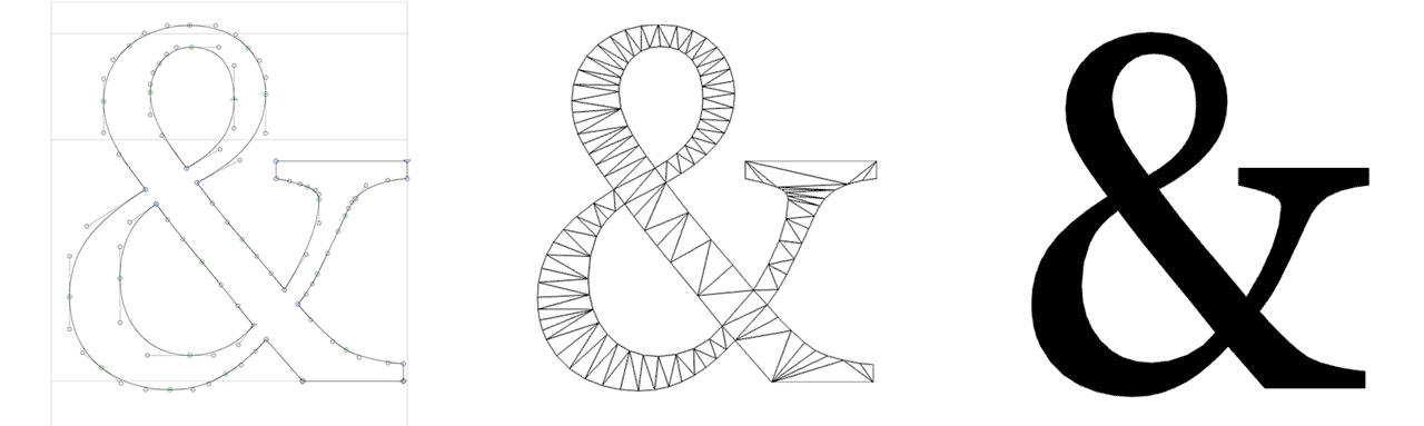
Tessellating a Glyph Path
Once we have flattened paths for all of our glyphs, the next step is to feed the flattened subpaths, or contours to libtess2 for tessellation. But first, let’s introduce the library itself.
The libtess2 library
The libtess library is a venerable piece of software originally written by Eric Veach in 1994. It was the reference implementation of the OpenGL Utility Library (GLU) tessellator, nicely described here. A newer incarnation with some extensions (and better performance) is maintained by Mikko Mononen as libtess2.
The purpose of libtess is simple enough to state: given a set of points, produce a tessellation that connects the points together into a planar mesh. Although tessellation in this context just means that the points are joined together into polygons, we want to ensure that the tessellation consists only of triangles, since we want to eventually feed a GPU with the results. Further restrictions will allow us to create a so-called Delaunay triangulation, which is a triangle-based tessellation that ensures the mesh has certain desirable properties.
The real power of libtess2, however, lies in its ability to ensure that certain edges are present in the output (producing a so-called constrained Delaunay triangulation). For the purposes of tessellating a glyph, this is important, because we need to ensure that only the interior of the glyph is tessellated. If we simply produced a Delaunay triangulation of the points along the glyph’s outline, there’s a high likelihood that many of its edges would intersect the glyph outline, which is no good for accurate drawing.
The libtess2 library has an elegant API that breaks down into a few different categories of function: object lifetime/configuration, contour submission, tessellation, and geometry retrieval.
Here’s the libtess2 API in its entirety. Of course, this is just the façade of many thousands of lines of code, but that’s the power of a well-designed API:
// Lifetime and configuration
TESStesselator *tessNewTess(TESSalloc *alloc);
void tessSetOption(TESStesselator *tess, int option, int value);
void tessDeleteTess(TESStesselator *tess);

// Contour submission
void tessAddContour(TESStesselator *tess, int size, const void *pointer, int stride, int count);

// Tessellation
int tessTesselate(TESStesselator *tess, int windingRule, int elementType, int polySize, int vertexSize, const TESSreal *normal);

// Geometry retrieval
int tessGetVertexCount(TESStesselator *tess);
const TESSreal *tessGetVertices(TESStesselator *tess);
const TESSindex *tessGetVertexIndices(TESStesselator *tess);
int tessGetElementCount(TESStesselator *tess);
const TESSindex *tessGetElements(TESStesselator *tess);
In the next subsection we’ll talk about how to put these functions to use.
Using libtess2
We create a tessellator object with the tessNewTess function, then configure it to produce constrained Delaunay triangulations:
TESStesselator *tessellator = tessNewTess(NULL);
tessSetOption(tessellator, TESS_CONSTRAINED_DELAUNAY_TRIANGULATION, 1);
Once we’ve created a tessellator object, we supply the constituent contours (subpaths) of each glyph with the tessAddContour function.
libtess2 is smart enough to know which paths are clockwise and which are counterclockwise. This is important because the winding of a contour determines whether the area it bounds is inside or outside the glyph. In this way, the “holes” in a glyph can be excluded from the triangulation.
The code for iterating over the subpaths of a CGPath is somewhat tedious (feel free to consult the sample code), but at the end of each subpath, we submit its set of constituent points to our tessellator. In the function call below, the second parameter indicates the number of components (2 for x, y), the third parameter is a pointer to the vertex data, the fourth parameter is the stride (number of bytes) between vertices, and the last parameter is the number of vertices in the contour:
tessAddContour(tessellator, 2, vertices, sizeof(PathVertex), vertexCount);
Once libtess knows all of the contours that constitute our glyph, we can tell it to do the real work of finding a tessellation:
tessTesselate(tessellator, TESS_WINDING_ODD, TESS_POLYGONS, 3, 2, NULL);
The second parameter, TESS_WINDING_ODD, indicates the winding rule (often called the fill rule) used to determine which portions of the union of the contours are “inside” the glyph. The third and fourth parameters combine to indicate that we want the output to be polygons, and that each polygon should have three vertices (i.e., be a triangle). The fifth parameter again indicates that our vertices have two components (x and y).
When this method returns, the tessellator holds the geometry of the tessellated mesh. We use the retrieval functions to get the vertex count, the vertex data, the number of indices, and the indices that indicate how the vertices should be stitched together into triangles:
int vertexCount = tessGetVertexCount(tessellator);
const TESSreal *vertices = tessGetVertices(tessellator);
int indexCount = tessGetElementCount(tessellator) * 3;
const TESSindex *indices = tessGetElements(tessellator);
Creating a Text Mesh
The data we get from the tessellator looks like something we could draw with Metal. In fact, we could load this data directly into buffers and draw it. There’s just one problem: this mesh is still planar. In order to give it some volume, we need to extrude it.
Extruding Geometry
Extrusion is the process of generating a mesh that duplicates a shape along a path and stitches the copies together to create a solid volume. In the case of this article, we’ll be extruding along a line segment, but it’s also possible to extrude along an arbitrary curve, producing interesting shapes.
Practically, the duplication step is achieved by literally making multiple copies of the vertex data in a vertex buffer. In the case of the sample code, we duplicate the tessellated mesh twice: once to create the front of the mesh, and once to create the back. The back faces are offset parallel to the Z axis to create the volume of the mesh. The normals of these vertices are set to the positive and negative Z axes, respectively. We also make two copies of the contour vertices in order to stitch the front and back faces together.
Stitching Extruded Copies
We already have the geometry for the front and back faces from the tessellator: in the case of the front faces, we use the index list as-is to create the triangle indices we’ll use to draw. In the case of the back faces, we need to flip the winding order so that the triangles face backwards in model space.
Stitching along the perimeter of the mesh is a matter of iterating the contours of each glyph and adding triangles that connect corresponding vertices in the front and back faces. This involves a lot of tedious pointer manipulation, but isn’t especially interesting, so I won’t show the code here. You’re welcome to consult the sample code if you’re curious.
From Model I/O to MetalKit
Once we have all of our mesh data written into a vertex buffer and index buffer, we can wrap them in an MDLMesh:
MDLSubmesh *submesh = [[MDLSubmesh alloc] initWithIndexBuffer:indexBuffer
    indexCount:indexCount
    indexType:MDLIndexBitDepthUInt32
    geometryType:MDLGeometryTypeTriangles
    material:nil];
NSArray *submeshes = @[submesh];
MDLMesh *mdlMesh = [self meshForVertexBuffer:vertexBuffer
    vertexCount:vertexCount
    submeshes:submeshes
    vertexDescriptor:vertexDescriptor];
As a final step, we use Model I/O and MetalKit interoperability to produce an MTKMesh, which we already know how to draw:
NSError *error = nil;
MTKMesh *mesh = [[MTKMesh alloc] initWithMesh:mdlMesh
    device:device
    error:&error];
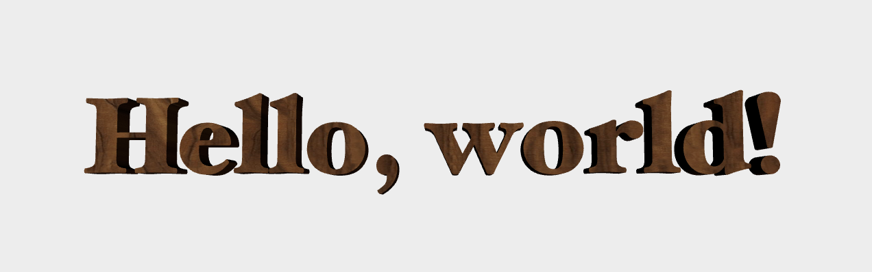
Here’s a look at the result of our labor: the phrase “Hello, world!” set in Hoefler Text Black, textured with a nice wood image. You can almost smell the leather-bound books and rich mahogany:

Conclusion
You can download the sample code for this article here.
In this article, we saw how to combine a pair of powerful libraries–Core Text and libtess2–to draw 3D text with Metal. Note that tessellation in general (and libtess2 specifically) can handle much more than text: any time you have paths (such as SVGs) to render on the GPU, you could consider tessellating them with libtess2. Such a triangulation could be used with Metal’s support for dynamic tessellation, to provide further refinement to meshed paths.
As always, comments and questions are welcome below.
Thanks to Caroline Begbie for proofreading.
- I’m being cavalier with terminology here, because this isn’t an article on digital typography. For our purposes, we will just treat Core Text as a machine that transforms strings into collections of paths to draw. ↩
- There is a higher-level object called a framesetter that does the work of adding line breaks and hyphenating, for the purposes of filling a rectangle (or other more complicated shape) with text. All of our text meshes will be a single line, so we won’t use a framesetter, but I mention it so that if you want to do more sophisticated text layout, you know where to look. ↩
-
Note that we could also have created an
NSAttributedStringand avoided some of these bridging casts, but we’d still have to bridge that string to its CF counterpart (CFAttributedStringRef) in order to create a typesetter. Sometimes, working with CF APIs is an exercise in figuring out where to put the casts. ↩ - A note on spelling: libtess2 spells “tesselate” with one “l” (as does the original libtess), while the more common spelling in American English uses two “l”s: “tessellate”. When writing about the API, I will use the spelling with a single “l”. In all other cases, I will stick with the two “l” spelling. ↩
Hi warren. Great article. I have one query. How do I extend your code to display multiple strings with different transformations?
You’d just need to have an array of
MTKMeshinstances on the renderer, and a corresponding array of their transforms. Then when drawing, you’d iterate over the meshes and write a distinct model-view matrix for each one to the constant buffer. It’s a pretty straightforward modification.Yes, I was able to achieve it. Thanks anyway.
Hi warren.
Excellent article.
I have a query. How to go about drawing the vertices obtained from libtess2 as triangle primitives instead of meshes ?
TIA.
You’re going to need to be more specific. The meshes rendered by this sample are composed of triangle primitives.
Sorry for asking to be spoonfed.
I am a newbie developer.
I have obtained the results till
int vertexCount = tessGetVertexCount(tessellator);
const TESSreal *vertices = tessGetVertices(tessellator);
int indexCount = tessGetElementCount(tessellator) * 3;
const TESSindex *indices = tessGetElements(tessellator);
I don’t want to render a Mesh.
How do I use the TESSreal *vertices to create triangles so that I can draw them directly using the metal API.
drawPrimitives(type:vertexStart:vertexCount:)
Thanks in advance, warren.
One way or another, you have to copy the vertices into a buffer so the vertex data is accessible to the GPU. And unless you really, really don’t want to use an index buffer, you’ll need to copy the indices into their own buffer too. If you absolutely do not want to use an index buffer, you’ll need to duplicate the vertices according to the indices before copying them into a Metal buffer. Each of these steps is fairly straightforward, but outside the scope of this post.
int vertexCount = tessGetVertexCount(tessellator);
const TESSreal *vertices = tessGetVertices(tessellator);
int indexCount = tessGetElementCount(tessellator) * 3;
const TESSindex *indices = tessGetElements(tessellator);
The vertices array is an array of float numbers.
I need to get some coordinates (x, y) to draw them as triangles.
I read through your code but could not figure out how to interpret the output from libtess as coordinates.
The vertices are just array of individual float numbers.
If you read the interface documentation for the
tessTesselatefunction, you’ll note that you can pass the preferred number of coordinates for each vertex (via thevertexSizeparameter). So although vertices is a pointer to an array of floats, you treat each adjacent set of 2 or 3 floats (depending on the parameter) as comprising a vertex.